
Preform for plastics material bottles or wide-necked vessels

Inactive Publication Date: 2010-12-02
ALPLA WERKE ALWIN LEHNER
View PDF18 Cites 21 Cited by
  • Summary
  • Abstract
  • Description
  • Claims
  • Application Information

AI Technical Summary

Benefits of technology

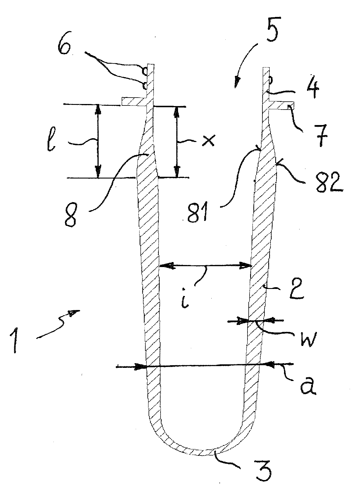
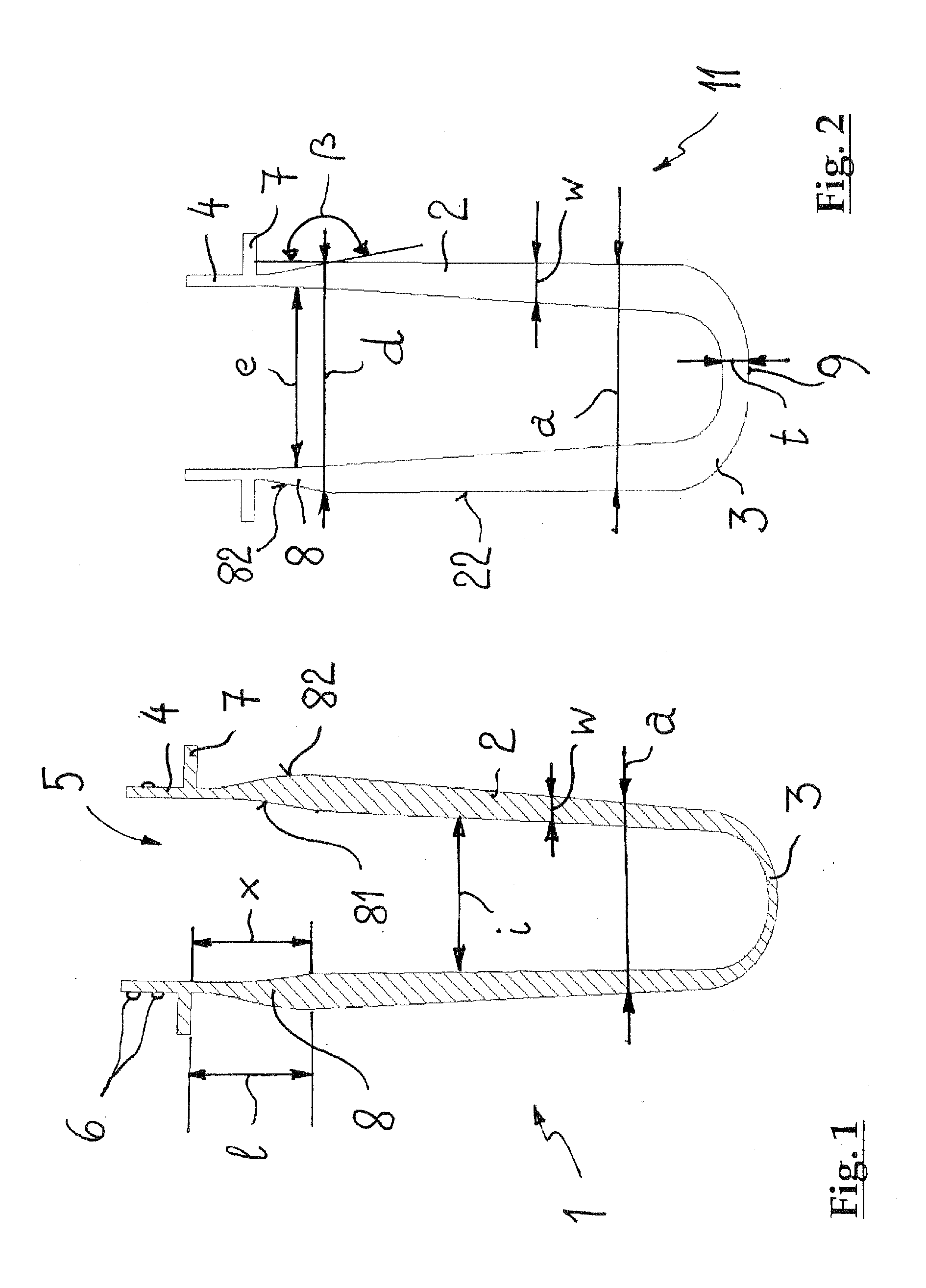
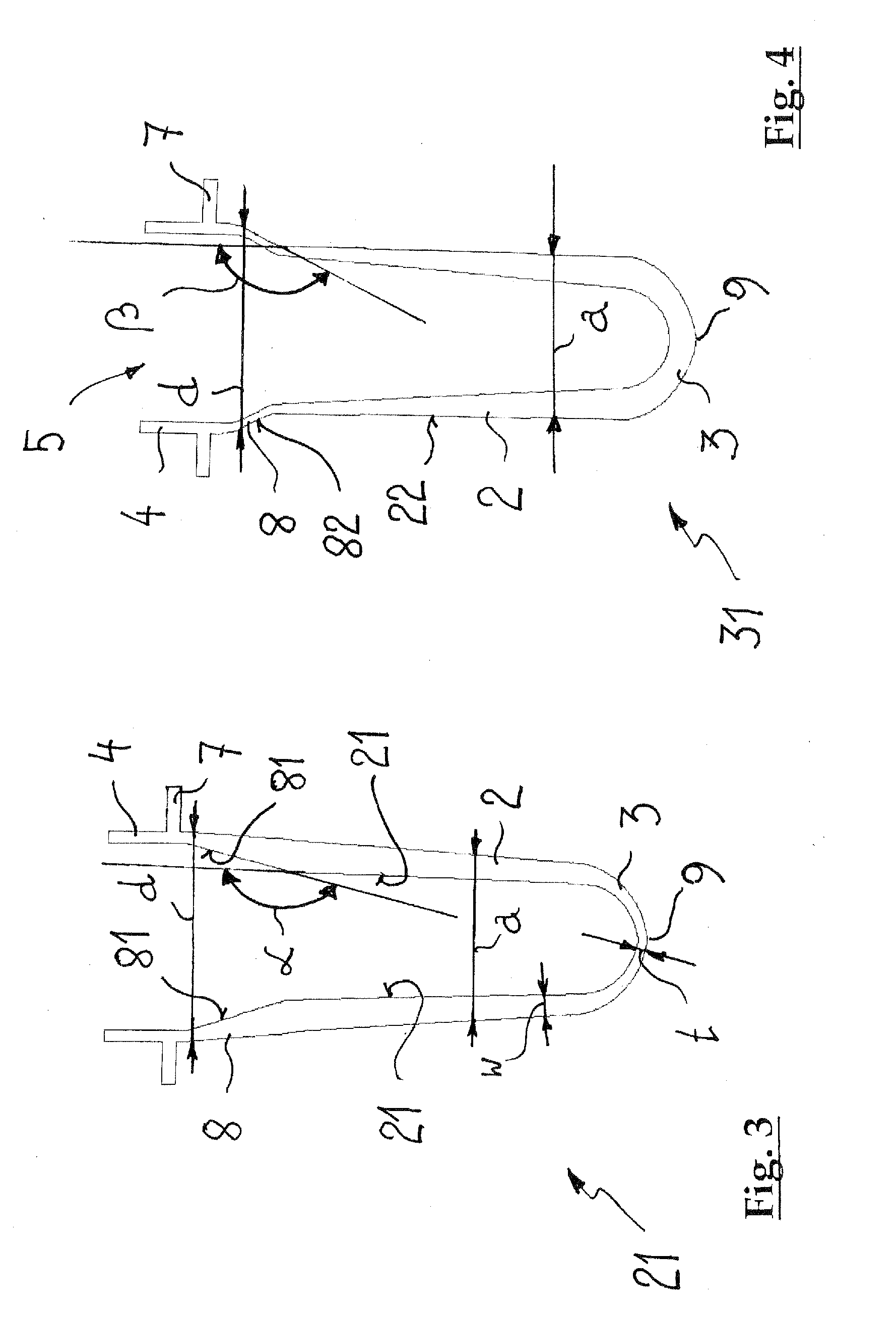
[0012]The fact that sudden changes in wall thickness are avoided makes allowance for the problem of local exposure to heat during the injecting of the preform with plastics material. This also ensures that the preform has uniform wall thicknesses over its circumference. Shrinkage cavities or the like, as a consequence of turbulences of the plastics material, at edges and corners can thus reliably be avoided. During stretch blow moulding of the preform, the forces are distributed more uniformly. Local overstressing, which might lead to material weakening, or overheating at edges and corners are as a result avoided. As a consequence of the substantially constantly preceding changes in wall thickness of merely up to 2 mm in the body portion of the preform (either an increase in wall thickness or a decrease in wall thickness by at most 2 mm from the transition of the preform collar up to the transition to the dome-shaped end portion), the behaviour of the plastics material during stretch blow moulding is easier to predict and to control. As a result, plastics material bottles or wide-necked vessels having the desired properties can be manufactured more reliably. Irrespective of the change in the wall thickness of the body portion, the internal diameter of the body portion decreases substantially constantly over its longitudinal extension toward the dome-shaped end portion. Undercuts are avoided, so that simple removability of the injection core from the mould continues to be ensured.
[0015]If the body portion of the preform has a minimum wall thickness which does not drop below 0.8 mm, sufficient rigidity and stability of the plastics material container made from the preform are ensured. On the other hand, the maximum wall thickness of the body portion does not exceed 6 mm. This ensures sufficiently rapid softening of the preform as a whole and uniform stretching of the body portion during the blow moulding method.
[0017]A sudden change in wall thickness is also avoided at the transition from the body portion to the end portion. For this purpose, the dome-shaped end portion has a wall thickness which is reduced from the wall thickness of the body portion up to an injection point by 0% to 50%, preferably 20 to 50%. The wall thickness in the injection point is in this case not taken into account. The wall thickness in the end portion is in this case selected in accordance with the type of bottom to be manufactured, in order to impart optimum rigidity and stability to the fully blow-moulded container.
[0020]Plastics material bottles and wide-necked vessels made from the preforms embodied in accordance with the invention are distinguished by high mechanical strengths and high thermal stability. For example, they allow the formation of a champagne bottom for the storage of highly carbonated beverages which can build up high pressure inside the bottle during storage or during transportation.

Problems solved by technology

During the manufacture of preforms of this type by injection moulding, the sudden change in wall thickness can lead to problems.
In particular, there can occur at the transition from the wall thickness of the body to the greater wall thickness of the bottom portion during the injection moulding method local temperature peaks which impair the properties of the plastics material.
In the stretch blow moulding method too, changes in the wall thickness of the preform, which are staggered in a stepwise manner, can lead to problems which manifest themselves as non-uniformities in the fully stretch blow-moulded plastics material bottle.
This also leads, in the known preforms, to staggered changes in wall thickness which can lead to the above-described problems.

Method used


Image

  • Preform for plastics material bottles or wide-necked vessels
  • Preform for plastics material bottles or wide-necked vessels
  • Preform for plastics material bottles or wide-necked vessels

Examples


Embodiment Construction

[0027]The preform illustrated in FIG. 1 is denoted in its entirety by reference numeral 1. It has a rigid, substantially elongate, frustoconically embodied body portion 2, one longitudinal end of which is closed by a dome-shaped end portion 3. The other longitudinal end of the body 2 is adjoined in the first place by what is known as a preform collar 8 which forms the transition of the body portion 2 to a neck portion 4 comprising a pouring opening 5. The neck portion 4 conventionally already displays the subsequent shape of the neck of the inflated plastics material bottle or a wide-necked vessel. Threaded portions 6 or the like are formed on the outside of the neck portion 4 for securing a closure part. The preform 1 is manufactured for example in an injection moulding method. Alternative manufacturing methods are for example extrusion or, with appropriate raw materials, spray foaming.

[0028]The preform collar 8 is separated from the neck portion 4 by an annularly encircling transp...


PUM

PropertyMeasurementUnit
Fractionaaaaaaaaaa
Fractionaaaaaaaaaa
Fractionaaaaaaaaaa

Abstract

A preform for manufacturing plastics material bottles or wide-necked vessels is described, having a rigid, substantially elongate, frustoconical body portion that is closed at one of its longitudinal ends by a dome-shaped end portion and at its opposite longitudinal end adjoins via a preform collar a neck portion provided with a pouring opening. The preform possesses in the body portion an external diameter that is reduced from the preform collar to the end portion. The body portion has a wall thickness which changes over its longitudinal extension substantially constantly by up to +2 mm. For this purpose, it possesses an internal diameter which decreases substantially constantly from a transition to the preform collar up to a transition to the dome-shaped end portion.

Description

BACKGROUND[0001]1. Field of the Invention[0002]The invention relates generally to a preform for plastics material bottles or wide-necked vessels, and more specifically to a perform having a rigid, substantially elongate, frustoconical body portion that is closed at one of its longitudinal ends by a dome-shaped end portion and at its opposite longitudinal end adjoins, via a preform collar, a neck portion provided with a pouring opening and has an external diameter that is reduced from the preform collar to the end portion.[0003]2. State of the Art[0004]The previously conventional containers made of white or coloured sheet metal, of glass or else of ceramic are increasingly being superseded by containers made of plastics material. In particular for the packaging of pourable media, for example of cleaning utensils, body care products, cosmetics, motor vehicle media, etc., use is made mainly of plastics material containers. The low weight and the relatively low costs are no doubt key fa...

Claims


Application Information

Patent Timeline
IPC IPC(8): B65D23/00
CPCB29B11/14B29B2911/1402B29B2911/14026B29B2911/14033B29B2911/1404B29B2911/14106B29B2911/14133B29B2911/1416B29B2911/1424B29B2911/14326B29B2911/14333B29B2911/1444B29B2911/1448B29B2911/14633B29B2911/1464B29B2911/147B29B2911/1482B29C49/06B29B11/08B29B11/10B29C2949/3024B29C2949/26B29C2949/28B29C2949/24B29C2949/22B29C2949/3032B29C2949/3041B29C2949/3064B29C2949/073B29C2949/0779B29C2949/072B29C2949/0773B29C2949/0818B29C2949/0817B29C2949/0827B29C2949/0845B29C49/071B29C2949/0715
Inventor DORNBACH, CHRISTIAN
Owner ALPLA WERKE ALWIN LEHNER
Learn More