
Device for the regulation of driving dynamics

a technology for driving dynamics and devices, applied in the direction of braking systems, process and machine control, instruments, etc., to achieve the effect of increasing the degree of driving dynamics regulation and ensuring safety for the occupants of the vehicle during the operation

Inactive Publication Date: 2010-12-02
CONTINENTAL TEVES AG & CO OHG
View PDF14 Cites 3 Cited by
  • Summary
  • Abstract
  • Description
  • Claims
  • Application Information

AI Technical Summary

Benefits of technology

The invention proposes a device for regulating the driving dynamics of a vehicle that can insulate the valve block from vibrations and sound. This leads to increased comfort for the passengers of the vehicle. The device includes an electronic regulator unit that is connected to the vehicle chassis through a support base, with damping elements between the regulator unit and the valve block. The valve block is also connected to the pump motor of the hydraulic pump, which is also insulated from vibrations and sound. The electronic regulator unit has sensors for driving dynamics that are connected to the vehicle chassis or the regulator unit in a rigid fashion. The device can achieve better insulation by using a flexible printed circuit board or elastic connections between the regulator unit and the valve block. The frequency range of the vibration insulation is between 8 Hz and 20 kHz. The housing of the regulator unit acts as a damping element to further improve the insulation.

Problems solved by technology

However, this compact design makes contradictory requirements of the design principle in terms of achieving best possible acoustic insulation of the valve block on the one hand and, on the other hand, provision of the most rigid possible connection to the vehicle chassis of the electronic regulator unit in order to be able to detect the driving dynamics of the vehicle satisfactorily by means of sensors.

Method used


Image

  • Device for the regulation of driving dynamics
  • Device for the regulation of driving dynamics

Examples


Embodiment Construction

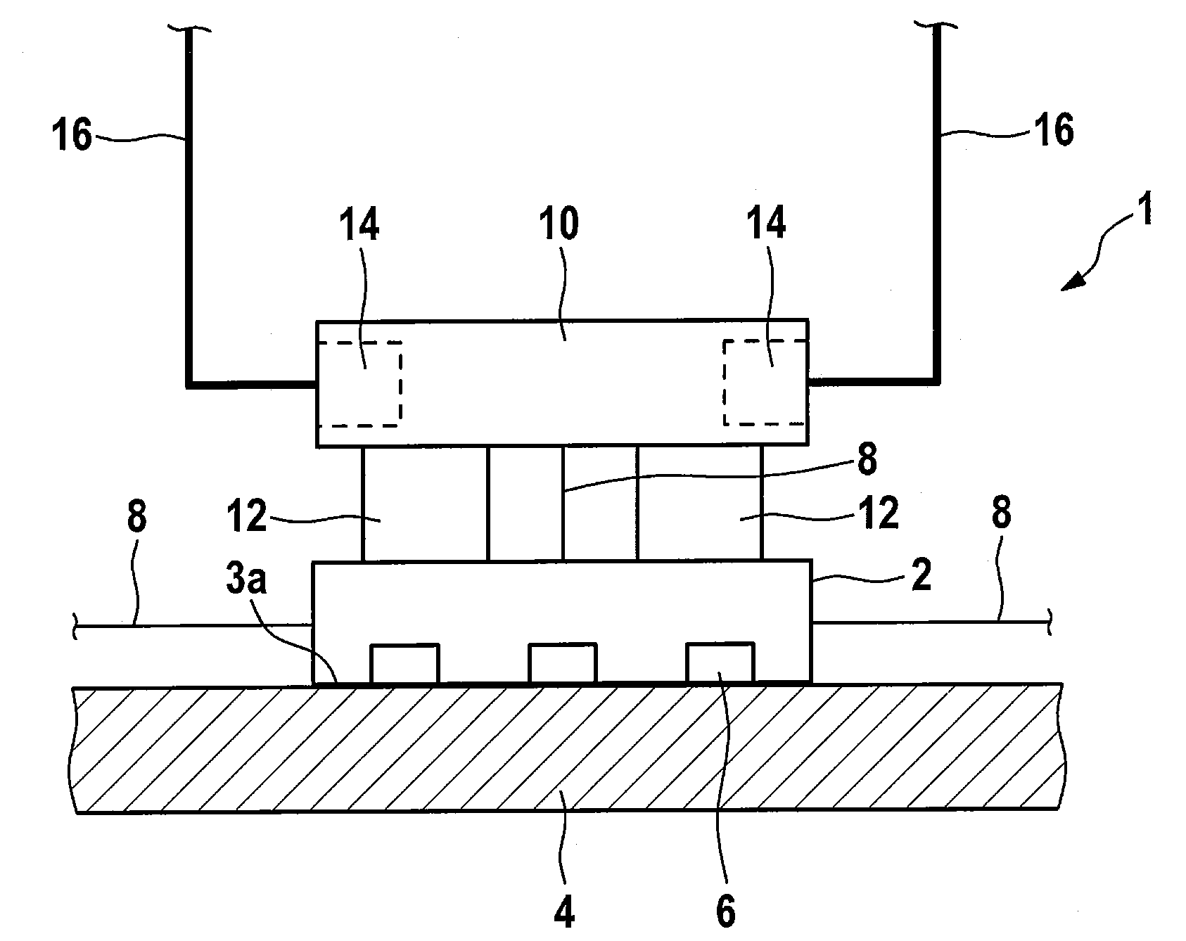
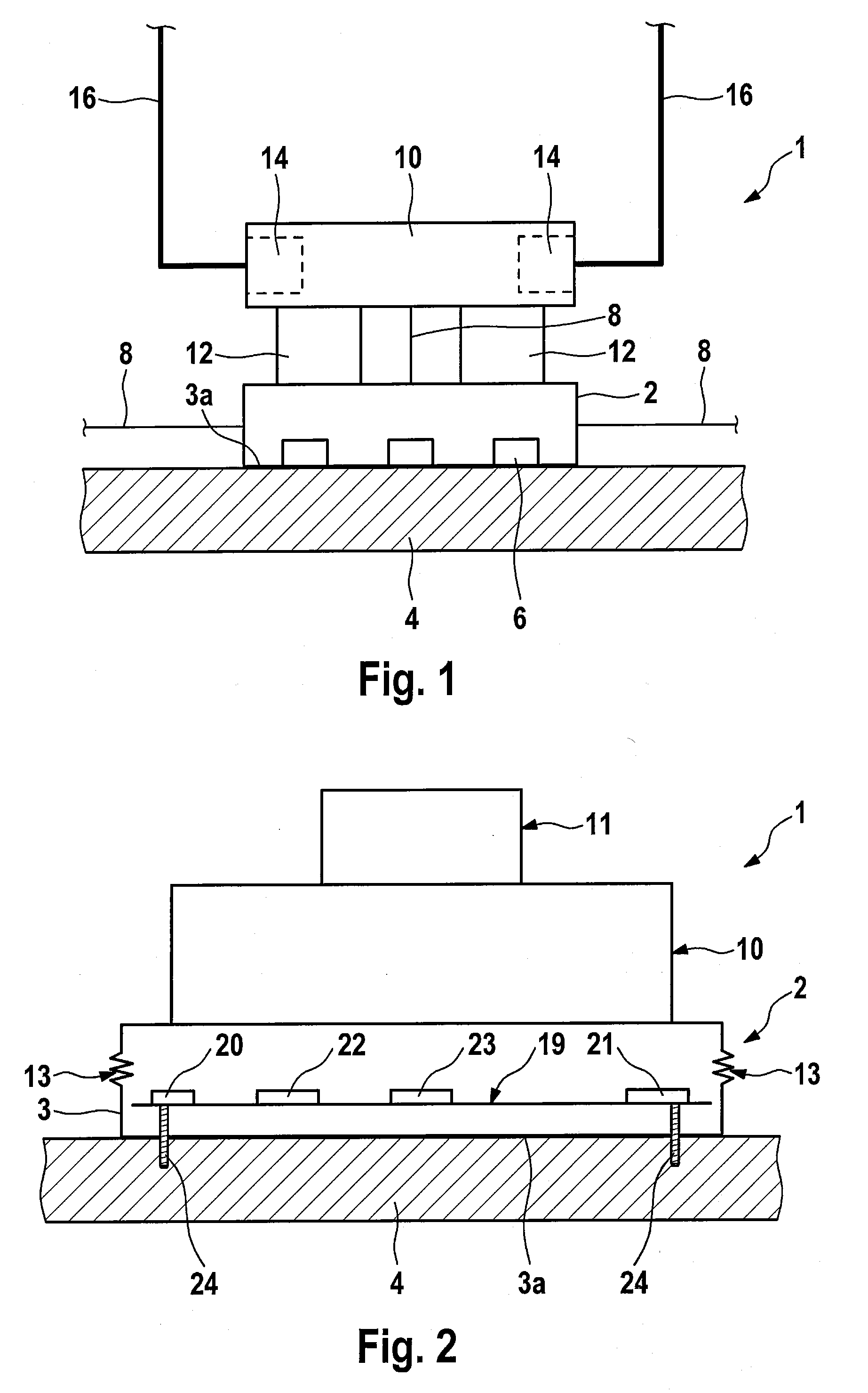
[0032]The exemplary driving dynamics regulator 1 according to FIG. 1 comprises an electronic regulator unit 2 which is mounted on the vehicle chassis 4. This electronic regulator unit comprises a number of driving dynamics sensors 6 which are attached to the regulator housing floor 3a and are therefore coupled relatively directly to the vehicle chassis 4 in terms of the transmission of sound or vibrations. Furthermore, signal lines 8, which transmit signals from further driving dynamics sensors, which are situated at different locations on the vehicle, to the electronic regulator unit 2.

[0033]A valve block 10 is mounted on the electronic regulator unit via damping elements 12. The valve block 10 has here a number, in the exemplary embodiment two, of valves 14 to which hydraulic lines 16 are connected. The commands which are output by the electronic regulator unit 2 by evaluating the signals received from the driving dynamics sensors are transmitted, for the control of the valves, fr...


PUM


Abstract

A device for the regulation of driving dynamics of a vehicle with an electronic regulator unit and a valve block. The electronic regulator unit is constructed as a support base for attaching the valve block to the vehicle chassis.

Description

CROSS REFERENCE TO RELATED APPLICATIONS[0001]This application is the U.S. national phase application of PCT International Application No. PCT / EP2008 / 066343, filed Nov. 27, 2008, which claims to priority to German Patent Application No. 10 2007 057 043.2, filed Nov. 27, 2007, the contents of such applications being incorporated by reference herein.FIELD OF THE INVENTION[0002]The invention relates to a device for the regulation of driving dynamics of a vehicle, and to its use in motor vehicles.BACKGROUND OF THE INVENTION[0003]DE 197 55 431, which is incorporated by reference, describes a system for the regulation of driving dynamics in which a sensor module for driving dynamics sensors, comprising yaw rate sensors and acceleration sensors, is arranged in an electronic housing which is arranged separately from the hydraulic controller, wherein the driving dynamics electronics which are integrated into the brake electronics are arranged in this housing. The hydraulic controller is conne...

Claims


Application Information

Patent Timeline
Patent Type & Authority Applications(United States)
IPC IPC(8): G06F19/00
CPCF16F15/02B60T8/3685
Inventor GIERS, BERNHARD
Owner CONTINENTAL TEVES AG & CO OHG
Learn More