Robust Manual Connector for Robotic Arm End Effector

a robotic arm and end effector technology, applied in the direction of arms, rod connections, manufacturing tools, etc., can solve the problems of limiting the effectiveness of the robot to those missions, and unsuitable for tasks that vary too widely from its essential purpose, so as to facilitate the engagement of teeth

Inactive Publication Date: 2010-12-09
RE2
View PDF99 Cites 47 Cited by
  • Summary
  • Abstract
  • Description
  • Claims
  • Application Information

AI Technical Summary

Problems solved by technology

Factory installed tools can only be repaired or replaced in a factory.
This limits the effectiveness of the robot to those missions which can be achieved with a single tool.
This has resulted in a proliferation of small UGVs, each performing admirably on tasks within each of its subset of core competencies, but is generally unsuitable for tasks that vary too widely from its essential purpose.
It is impractical to expect field teams to carry multiple UGVs, each suited for a specific task.
This reduces the ability of the operator to capitalize on the experience and intuition gained from operating previous robots, because the operator cannot rely on the trained reflexes developed while controlling previous robots.
In fact, these differing control schemes lead to operator errors and inefficient control.
Another approach has been to design new, more capable robots, but this approach has drawbacks because even if a robot were designed and built to perform all of the tasks currently assigned to UGVs, it would quickly become outdated as new tasks and jobs are identified.
Additionally, external variables, such as physical environment, make UGVs designed for one environment wholly impractical for use in another environment, meaning a number of new robot types would need to be designed, tested, and built.
Systems with replaceable end effectors are also ineffective because they require a technician and possibly a number of specialty tools.
Particularly, in time critical applications, such as military or civilian Explosives Ordinance Disposal (EOD), this process is too slow and interferes with missions.
In addition, unlike industrial robots, these systems are deployed in uncontrolled environments.

Method used


Image

  • Robust Manual Connector for Robotic Arm End Effector
  • Robust Manual Connector for Robotic Arm End Effector
  • Robust Manual Connector for Robotic Arm End Effector

Examples


Embodiment Construction

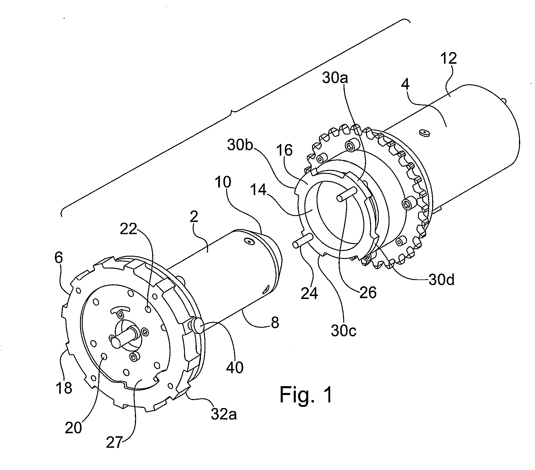
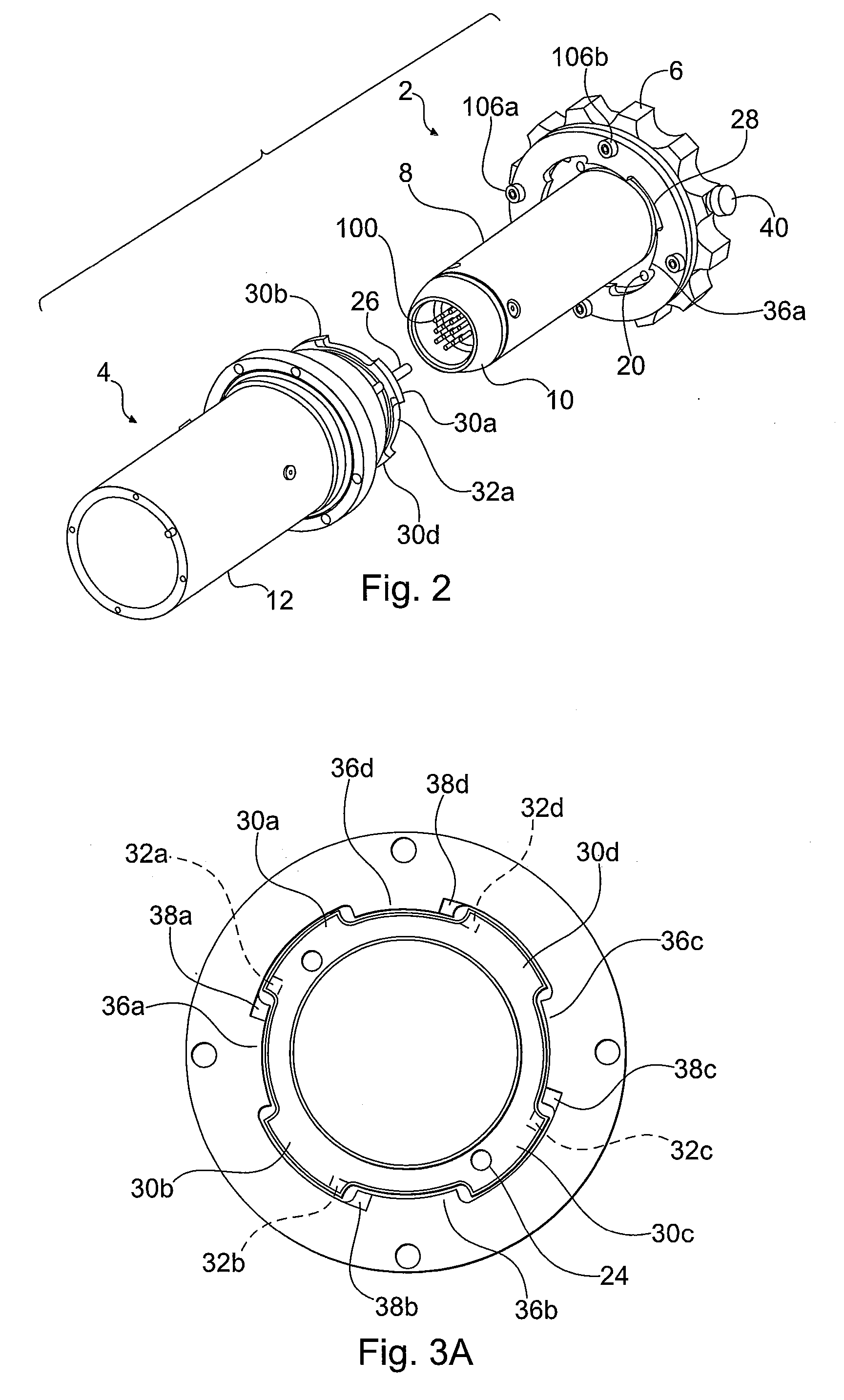
[0034]These and other features and characteristics of the present invention, as well as the methods of operation and functions of the related elements of structures and the combination of parts and economies of manufacture, will become more apparent upon consideration of the following description and the appended claims with reference to the accompanying drawings, all of which form a part of this specification, wherein like reference numerals designate corresponding parts in the various figures. It is to be expressly understood, however, that the drawings are for the purpose of illustration and description only and are not intended as a definition of the limits of the invention. As used in the specification and the claims, the singular form of “a”, “an”, and “the” include plural reference unless the context clearly dictates otherwise.

[0035]The quick-release assembly provides a light-weight mechanical coupler to change-out tools to a robotic manipulator. The mechanical coupler can ri...


PUM

PropertyMeasurementUnit
displacementaaaaaaaaaa
lengthaaaaaaaaaa
rotationaaaaaaaaaa

Abstract

The present invention is an assembly for releasably connecting an end effector in the form of a robotic tool or component to a robotic arm. The connection is manually operated and formed of a first and second joint member including a cylindrical body, a locking collar, and a locking wall extending from the cylindrical body. The locking collar is coaxially aligned with and rotatably connected to the first joint member. The second joint member has a cylindrical mating body and a coupler, and engages the first joint member. The coupler also includes key pins, the pins being engageable in keyed relationship with the locking wall, the coupler and locking collar further includes intervening circumferentially spaced teeth, wherein the collar is rotatable to releasably engage the first joint member with the second joint member.

Description

CROSS REFERENCE TO RELATED APPLICATIONS[0001]This application is based on U.S. Provisional Patent Application No. 61 / 268,085, filed Jun. 8, 2009, on which priority of this patent application is based and which is hereby incorporated by reference in its entirety.BACKGROUND OF THE INVENTION[0002]Manipulators on mobile robots often require specialized end effectors (tools / components) in order to accomplish particular missions. Currently, deployed systems have end effectors designed, built, and installed at the factory. Factory installed tools can only be repaired or replaced in a factory. This limits the effectiveness of the robot to those missions which can be achieved with a single tool. Heretofore, when a new candidate task is identified, the typical response has been to design and build a new robot intended to perform the specific task. Sometimes existing unmanned ground vehicles (UGV) platforms are used, but just as often, a new robot is created to specifically address the task. T...

Claims


Application Information

Patent Timeline
Patent Type & Authority Applications(United States)
IPC IPC(8): B25J17/00B23P11/00F16B7/06
CPCB25J15/04Y10S901/30Y10T29/49947Y10T403/295Y10T74/20329Y10S901/50Y10T403/7007
Inventor CAMPAGNA, FRANK F.RIZK, NABIL MICHAELGUNNETT, KEITH M.
Owner RE2
Why Eureka
Try Eureka