
Protection system

a protection system and countermeasure technology, applied in the field of countermeasure systems, can solve the problems of rpg's and other threats used by enemy forces and insurgents, serious threat to troops on the battlefield, in open country, and in city streets, and achieve the effect of effective and reliabl

Active Publication Date: 2010-12-09
FOSTER-MILLER
View PDF35 Cites 64 Cited by
  • Summary
  • Abstract
  • Description
  • Claims
  • Application Information

AI Technical Summary

Benefits of technology

"The invention is a protection system for vehicles and structures that uses a net and a manifold assembly with inflator charges to deploy the net in the path of an incoming threat. The system is designed to be effective, reliable, easy to install and remove, and inexpensive. The net is folded in a channel in the housing and is fixed to the housing with attachments. The inflator charge is activated to inflate the bladder and deploy the net. The technical effect of the invention is to provide a flexible and effective protection system that can be easily installed and removed."

Problems solved by technology

Rocket Propelled Grenades (RPGs) and other threats used by enemy forces and insurgents are a serious threat to troops on the battlefield, on city streets, and in open country.
RPG's pose a persistent deadly threat to moving ground vehicles and stationary structures such as security check points.
Heavily armored, lightly armored, and unarmored vehicles have been proven vulnerable to the RPG shaped charge.
Today, the RPG threat in Iraq is present at every turn and caches have been found under bridges, in pickup trucks, buried by the road sides, and even in churches.
Armor plating on a vehicle does not always protect the vehicle's occupants in the case of an RPG impact and no known countermeasure has proven effective.
Certain prior art discloses the idea of deploying an airbag (U.S. Pat. No. 6,029,558) or a barrier (U.S. Pat. No. 6,279,449) in the trajectory path of a munition to deflect it but such countermeasure systems would be wholly ineffective in the face of a RPG.
Many such interception systems are ineffective and / or expensive, complex, and unreliable.

Method used


Image

  • Protection system
  • Protection system
  • Protection system

Examples


Embodiment Construction

[0038]Aside from the preferred embodiment or embodiments disclosed below, this invention is capable of other embodiments and of being practiced or being carried out in various ways. Thus, it is to be understood that the invention is not limited in its application to the details of construction and the arrangements of components set forth in the following description or illustrated in the drawings. If only one embodiment is described herein, the claims hereof are not to be limited to that embodiment. Moreover, the claims hereof are not to be read restrictively unless there is clear and convincing evidence manifesting a certain exclusion, restriction, or disclaimer.

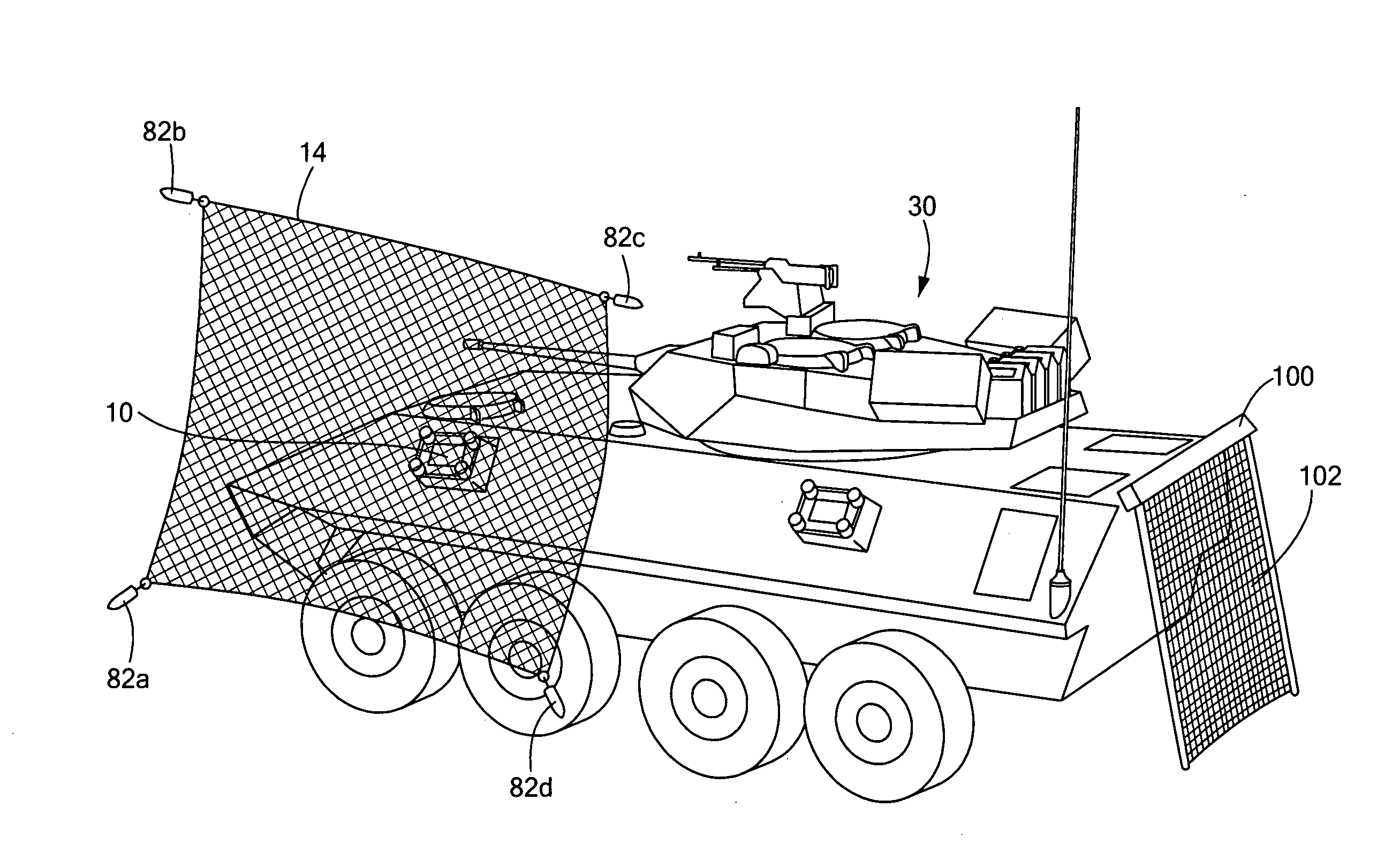
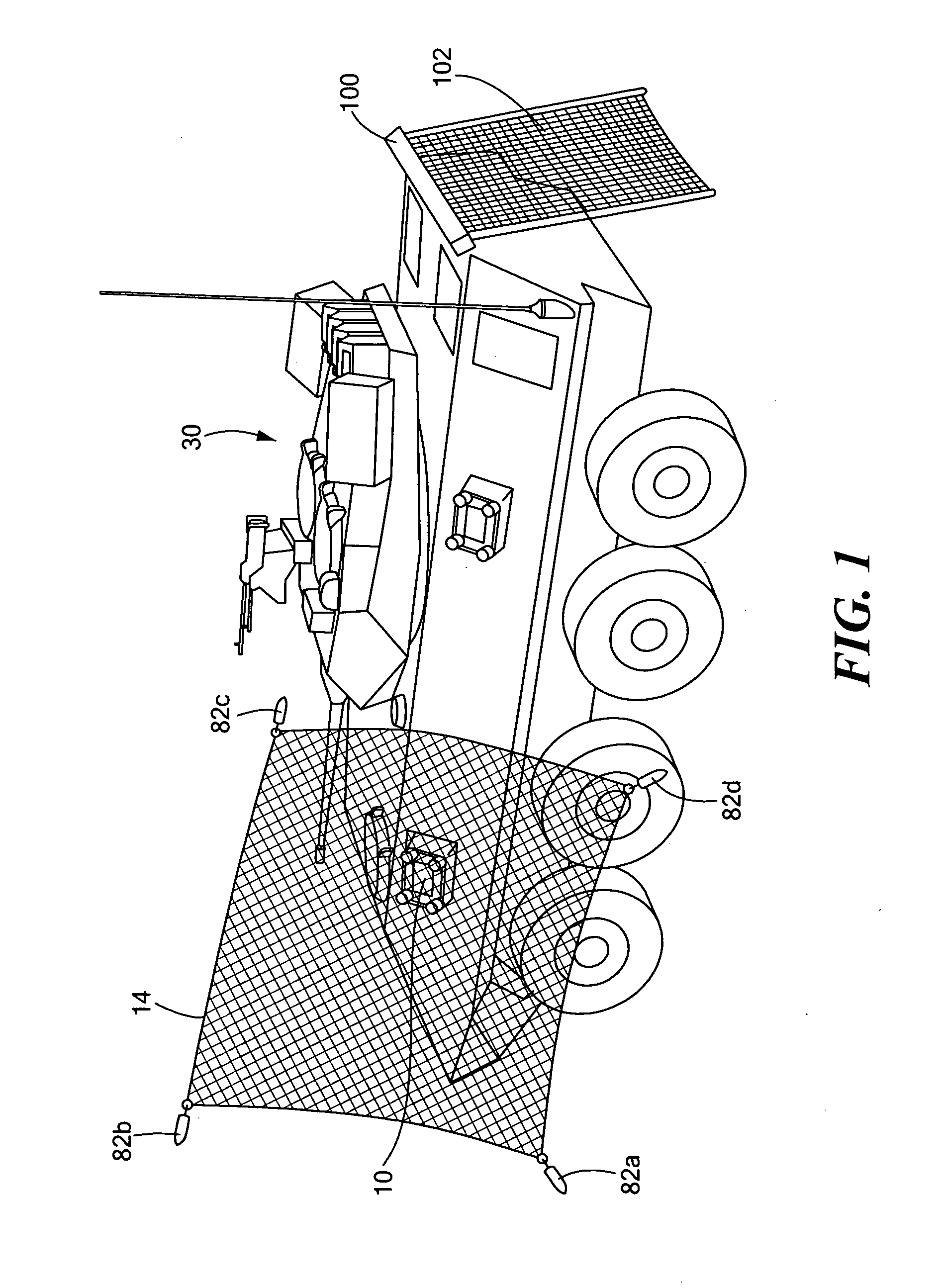
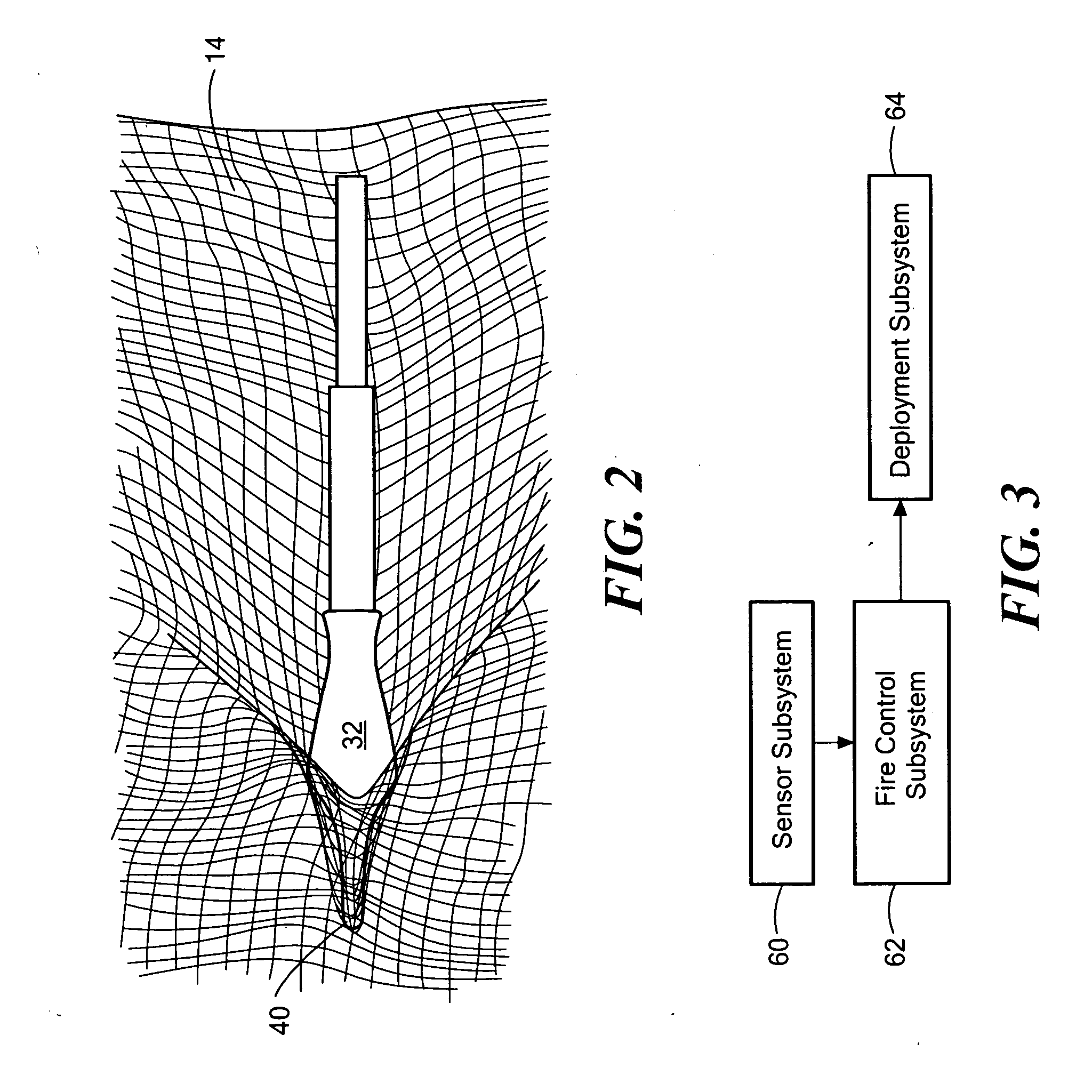
[0039]In one specific embodiment, a vehicle or structure protection system in accordance with the subject invention includes deployment box 10, FIG. 1 releasably attached to the exterior of vehicle or other structure in any desired location. In this way, the protection system of this invention can be used as desired on any ...


PUM


Abstract

A net deployment system which, in one example, includes a manifold assembly including multiple weight ducts and a bladder port. A weight is disposed in each weight duct and each weight is tied to the net. A bladder is behind the net and is over the bladder port. At least one inflator charge is associated with the manifold for inflating the bladder and firing the weights out of the weight ducts to deploy the net in the path of an incoming threat.

Description

RELATED APPLICATIONS[0001]This application is a divisional of prior U.S. patent application Ser. No. 11 / 890,946 filed Aug. 8, 2007, which is a continuation-in-part application of U.S. patent application Ser. No. 11 / 351,130, filed Feb. 9, 2006. This application claims the benefit of and priority to U.S. patent application Ser. Nos. 11 / 890,946 and 11 / 351,130 which are incorporated herein by reference.GOVERNMENT RIGHTS[0002]This invention was made with U.S. Government support under DARPA contract No. HR0011-05-C-0056. The Government may have certain rights in the subject invention.FIELD OF THE INVENTION[0003]This subject invention relates to counter measure systems and, in particular, to an easy to install, fairly inexpensive, and more effective vehicle protection system.BACKGROUND OF THE INVENTION[0004]Rocket Propelled Grenades (RPGs) and other threats used by enemy forces and insurgents are a serious threat to troops on the battlefield, on city streets, and in open country. RPG weapo...

Claims


Application Information

Patent Timeline
Patent Type & Authority Applications(United States)
IPC IPC(8): F41H11/00F41H13/00
CPCF41H5/007F41H13/0006F41H11/02F41H5/026
Inventor HOADLEY, DAVID J.KNOCHENHAUER, ROBERTTRUONG, THIEUANDERSON, GARYFARINELLA, MICHEAL
Owner FOSTER-MILLER
Learn More