Line dispensing device with eddy current breaking for use with climbing and evacuation

Active Publication Date: 2010-12-09
EDDY CURRENT PARTNERSHIP
View PDF13 Cites 43 Cited by
  • Summary
  • Abstract
  • Description
  • Claims
  • Application Information

AI Technical Summary

Benefits of technology

[0022]Yet another aspect of this disclosure describes a method for automatically feeding and retracting line. The method includes performing the following steps: providing a line for extension and retraction; applying a retraction force to the line with a retracting mechanism; and applying a braking force to the lin

Problems solved by technology

While the clutch is an effective mechanism for selectively engaging a braking system, prolonged use of the clutch will wear on the mechanism over time until the clutch is no longer safe and/or effective.
Because failure of a clutch often results in the braking system

Method used


Image

  • Line dispensing device with eddy current breaking for use with climbing and evacuation
  • Line dispensing device with eddy current breaking for use with climbing and evacuation
  • Line dispensing device with eddy current breaking for use with climbing and evacuation

Examples


Embodiment Construction

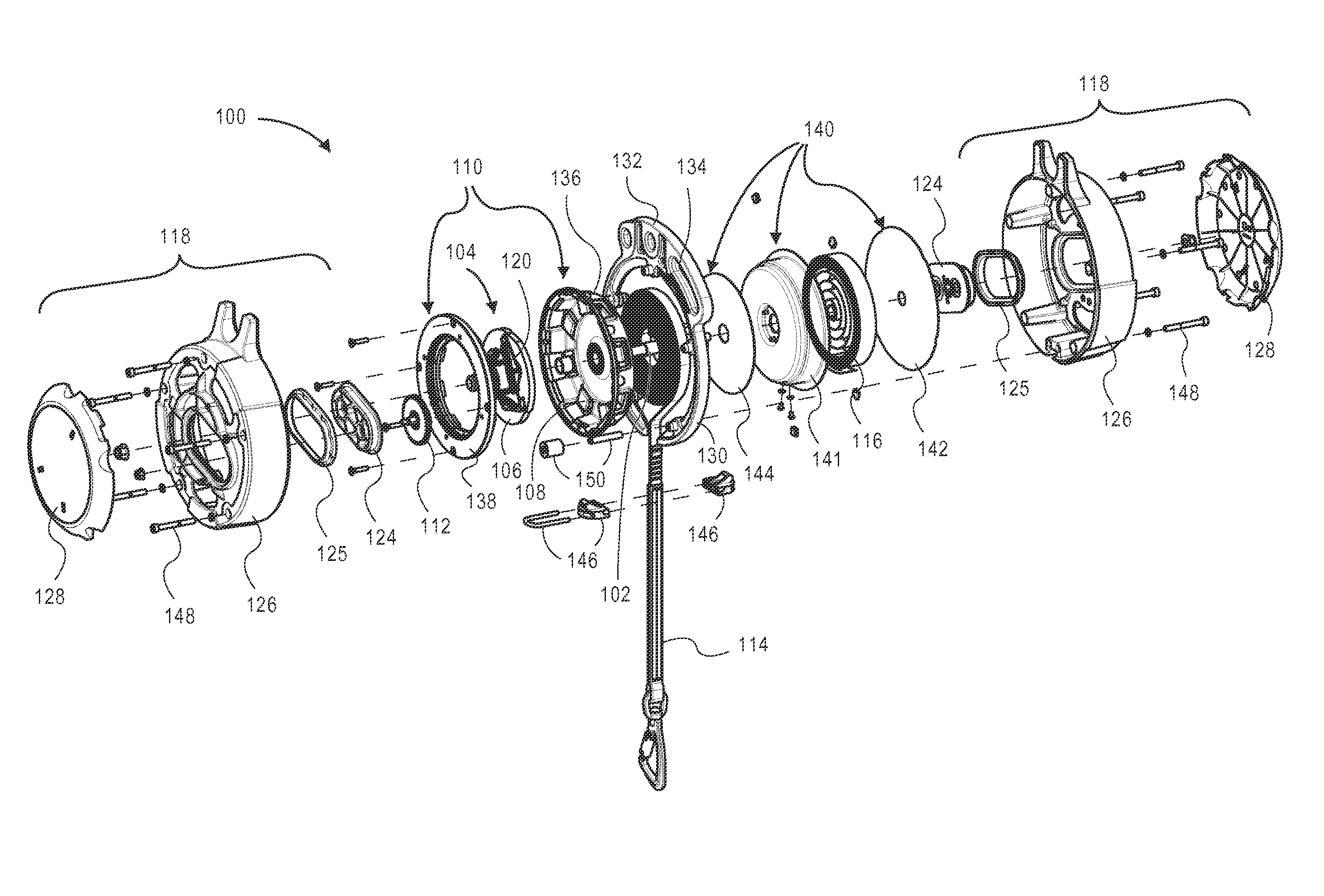
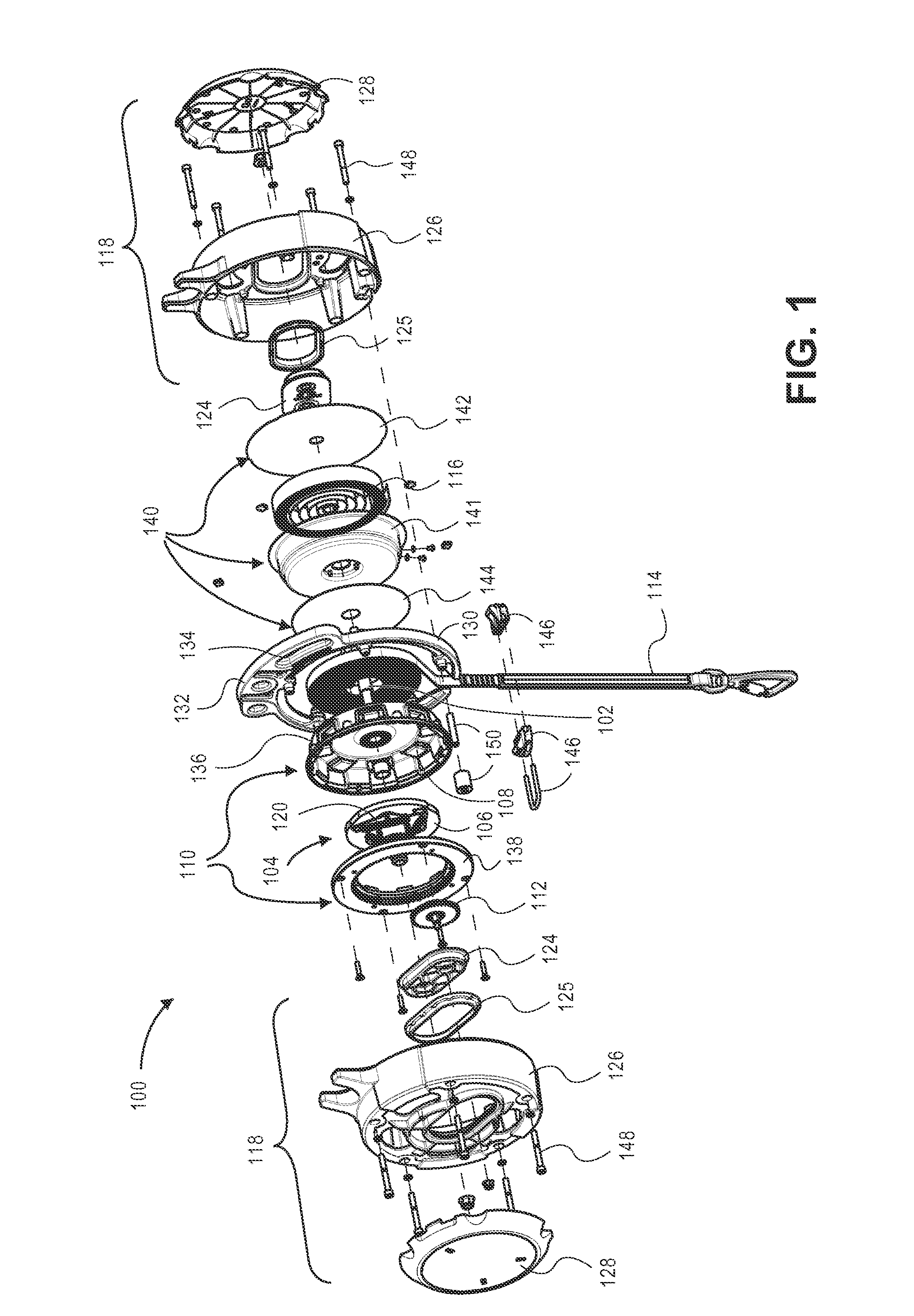
[0039]This disclosure describes embodiments of novel line dispensing devices and methods for dispensing and retracting a line of a line dispensing device.

[0040]In one embodiment an eddy-current braking mechanism includes a rotor, rotatable about a rotor axis; at least one electrically conductive member coupled to the rotor for rotation therewith; at least one magnet configured to apply a magnetic field extending at least partially orthogonal to the plane of rotation of the conductive member; and characterized in that upon rotation of the rotor, the conductive member is configured to move at least partially radially from the rotor axis into the applied magnetic field.

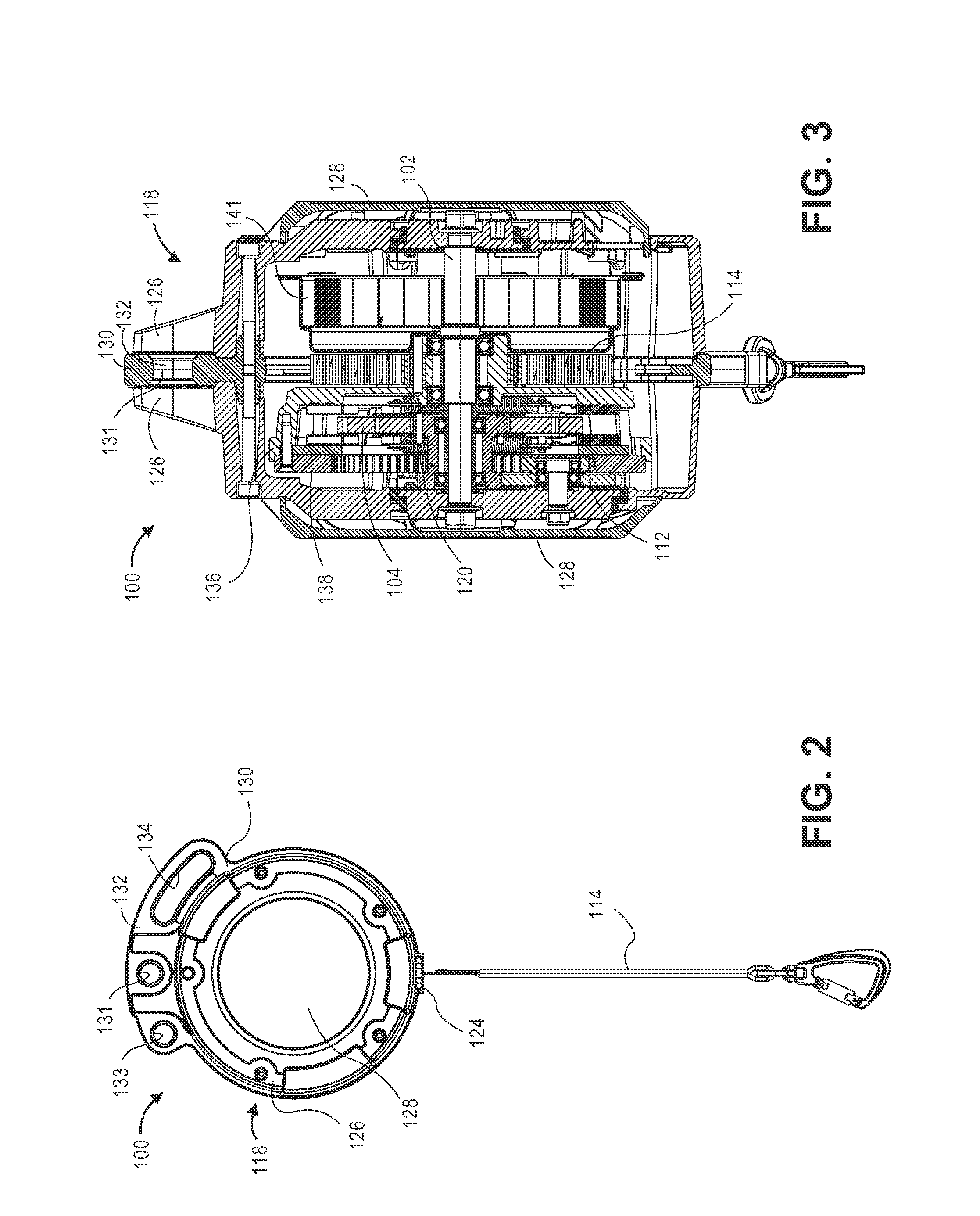
[0041]In general, movement of the conductive member through the applied magnetic field induces an eddy-current in the conductive member when the conductive member intersects the magnetic field.

[0042]To aid clarity and avoid prolixity, reference herein will be made to the conductive member being coupled to the rotor. Howe...


PUM


Abstract

This disclosure describes embodiments of novel line dispensing devices and methods for dispensing and retracting a line of a line dispensing device.

Description

RELATED APPLICATIONS[0001]This application is a continuation-in-part of prior of PCT Application No. PCT / NZ2010 / 000011, filed Jan. 29, 2010, and entitled, “Improvements in and relating to braking mechanisms”, which claims benefit of Serial No. 575464, filed Mar. 10, 2009 in New Zealand. To the extent appropriate, a claim of priority is made to each of the above disclosed applications.INTRODUCTION[0002]Line dispensing devices, such as auto-belay devices used for climbing, are used to protect against falls by retracting slack when the line is not under load and providing a braking force when the line is loaded, so that the weight on the end of the line is lowered at a safe speed. Several braking systems, such as a friction-brake or hydraulic dampening mechanism, have been utilized in line dispensing devices. These devices typically utilize a clutch to engage and disengage the braking system so that the braking system is completely disengaged from the rest of the device when the line i...

Claims


Application Information

Patent Timeline
IPC IPC(8): B65H75/48B65H75/44B65H75/40
CPCA62B1/08H02K7/116H02K16/005H02K49/046H02K7/12H02K2213/09A62B1/10H02K49/04H02K49/10H02K7/104F16D59/00A63B69/0048
Inventor ALLINGTON, CHRISTOPHER JAMESDIEHL, ANDREW KARLROBERTSON, BRUCE JOHN
Owner EDDY CURRENT PARTNERSHIP
Why Eureka
Try Eureka