

Planar inductive element
a technology of inductive elements and planar transformers, applied in the direction of inductances, inductances with magnetic cores, inductances, etc., can solve the problems of reducing the efficiency of magnetic elements, increasing the temperature of planar windings, and additional electromagnetic noise, so as to reduce the influence of fringing flux
- Summary
- Abstract
- Description
- Claims
- Application Information
AI Technical Summary
Benefits of technology
Problems solved by technology
Method used
Image

Examples
Embodiment Construction
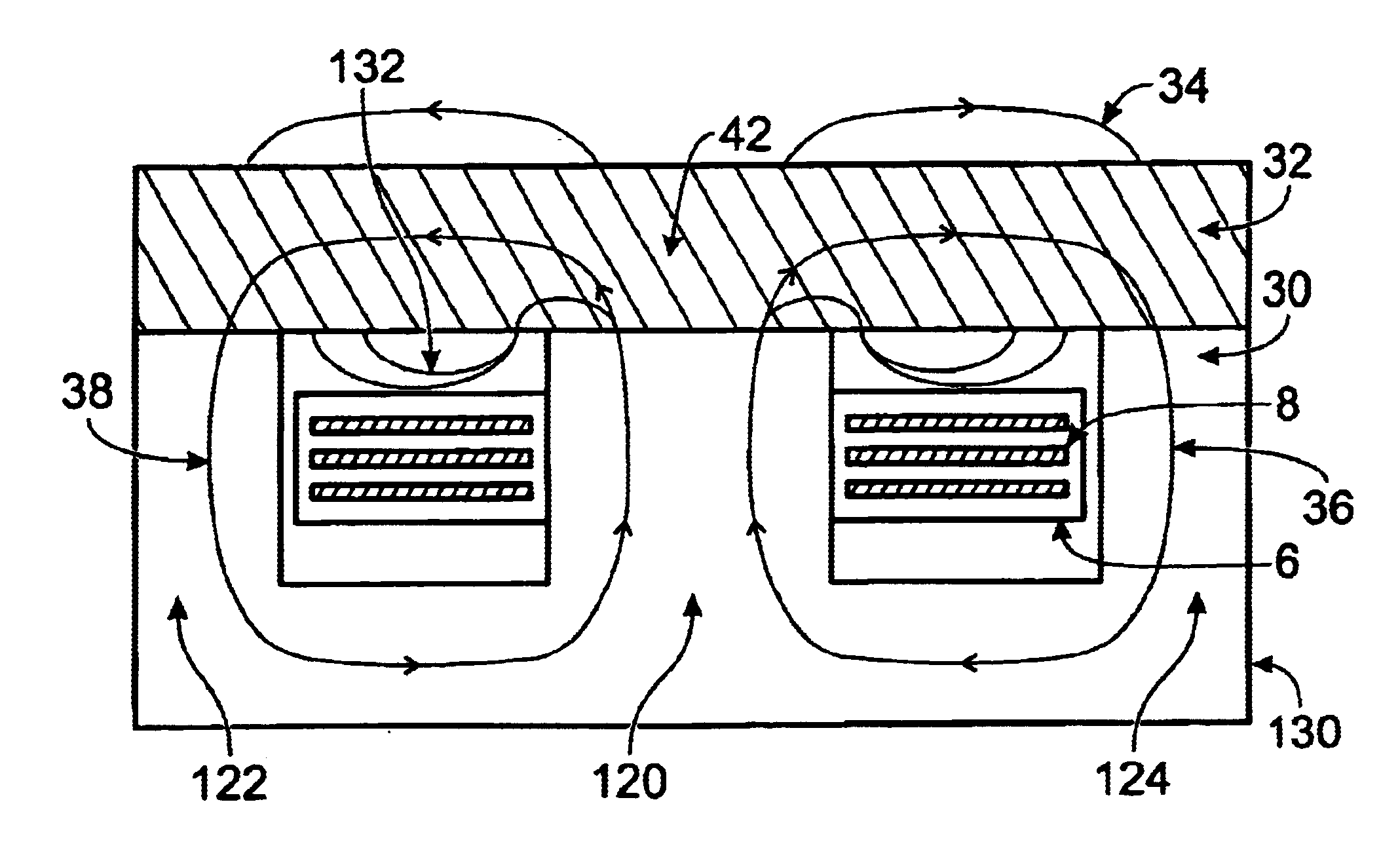
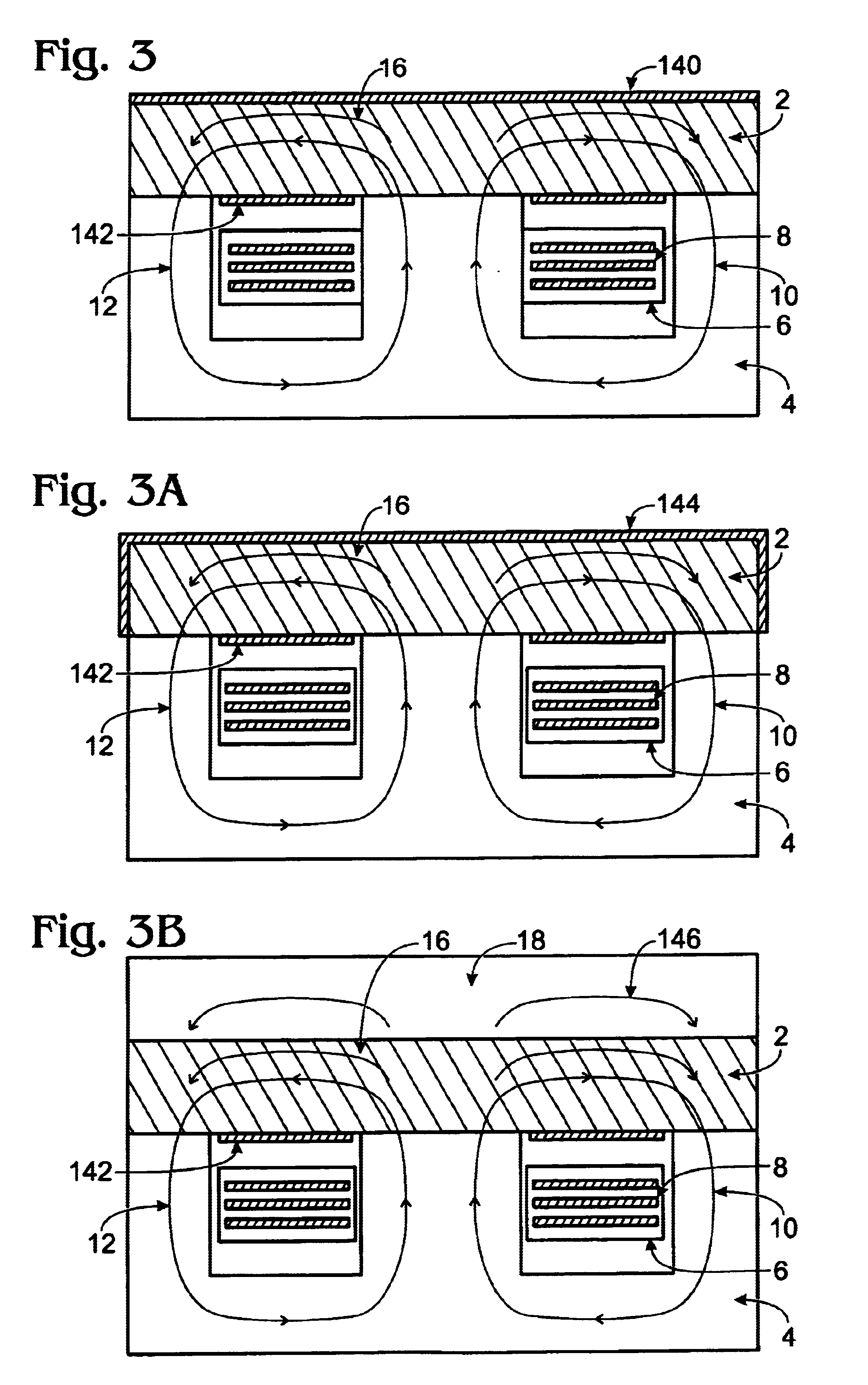
[0027]One approach presented in FIG. 3 uses a combination of an E magnetic core 4 made from a material with high magnetic permeability and an I core 2 made from a material which has energy storage capability. It can be a material, which provides a distributed gap such as iron powder material, cool-mu material or even a low permeability ferrite. The planar windings 8 are embedded into the printed circuit board 6. On the topside of the I core 2 and also on the bottom side, right into the winding window, there is a thin electrically conductive shield. The magnetic field lines 10 and 12 closed through the E magnetic core 4 and the I core 2. The top electrically conductive shield doesn't allow the magnetic field lines 16 to leave the inside of the I core 2. In addition the bottom electrically conductive shield doesn't allow the magnetic field lines to penetrate the planar embedded windings 8 and thus their AC resistance is not increased by an eddy currents distribution effect Hence the c...
PUM
 Abstract
Description
Claims
Application Information