
Active headrest apparatus for vehicle seat

a headrest and vehicle seat technology, applied in vehicle parts, pedestrian/occupant safety arrangements, vehicle arrangements, etc., can solve the problems of frequent neck injury of the person sitting in the car, severe shock to the joint and muscle of the neck, and neck joint injury, so as to achieve more stably and faithfully the effect of the active headres

Active Publication Date: 2010-12-09
DYMOS
View PDF6 Cites 20 Cited by
  • Summary
  • Abstract
  • Description
  • Claims
  • Application Information

AI Technical Summary

Benefits of technology

[0019]The present invention provides an active headrest apparatus for a vehicle seat having an improved structure in which a contact area in which the upper body of a person who is seated in a car in the event of a rear-end collision of the car is moved backward due to an inertial force and contacts a back plate is increased so that the function of an active headrest can be more stably and faithfully performed.
[0020]The present invention also provides an active headrest apparatus for a vehicle seat having a function of a stopper in which a headrest that is moved and rises in a direction to the head of a person who is seated in a car in the event of a rear-end collision of the car can be constantly maintained in its original state so that neck injury of a person who is seated in a car can be more effectively prevented to the maximum.

Problems solved by technology

In the event of a rear-end collision of the car that stops, neck injury of the person who is seated in the car occurs frequently.
The shearing force causes severe shock to the joint and muscle of the neck and injury of the joint of the neck.
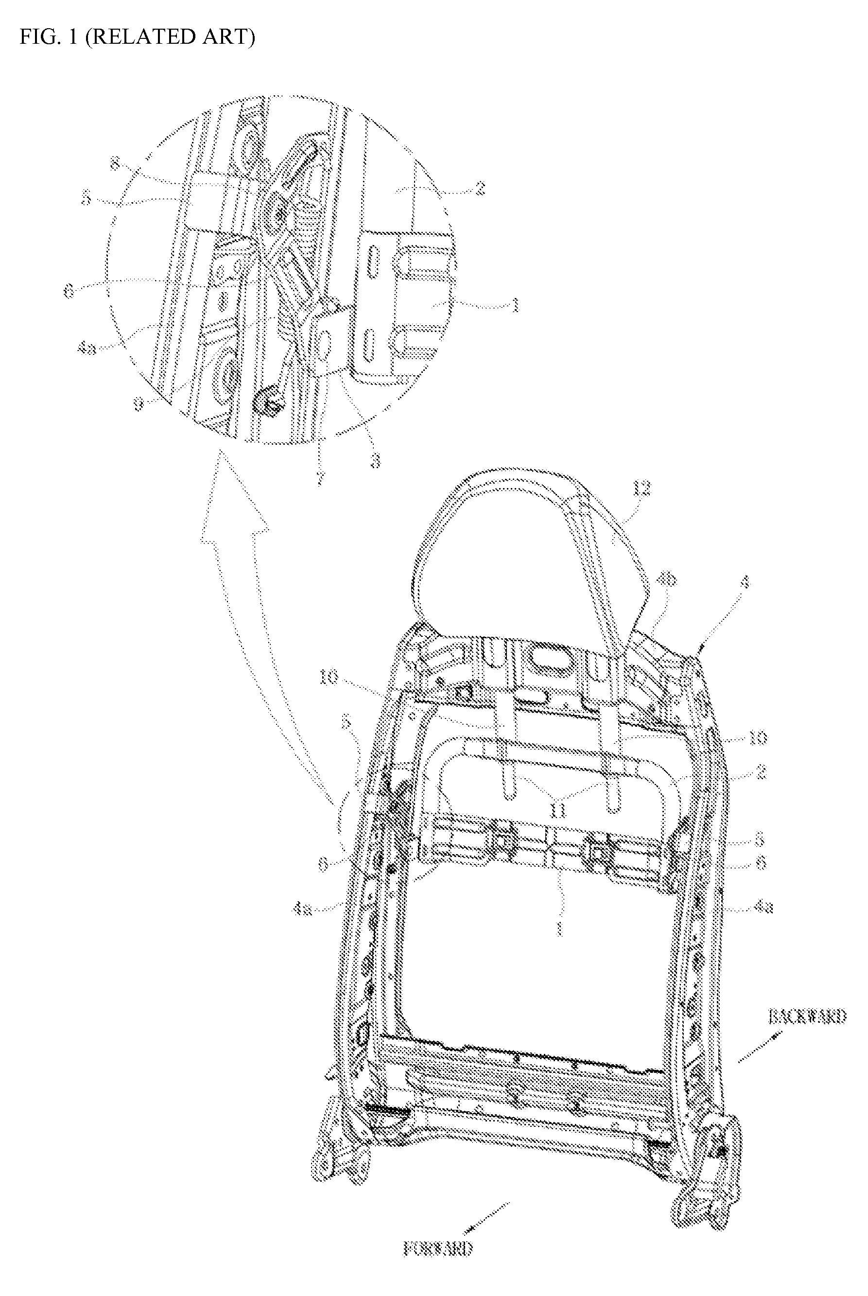
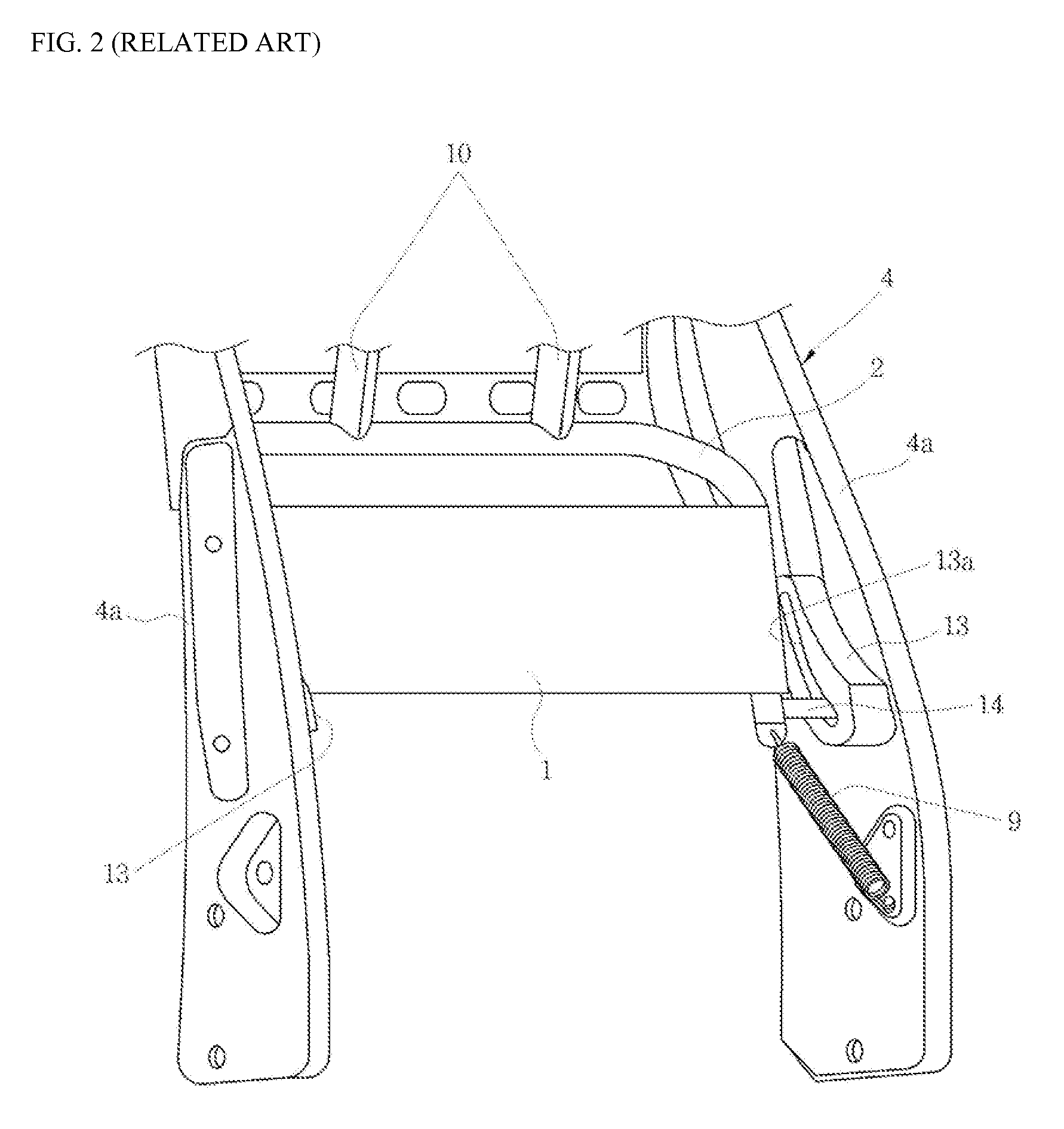
However, even in the conventional active headrest apparatus illustrated in FIG. 2, since the guide member 13 protrudes toward an inside of the seat back frame 4a, the same problem as the conventional active headrest apparatus illustrated in FIG. 1 occurs.
However, in that case, the strength of the side frames 4a is greatly reduced, and due to the side frames 4a with the reduced strength, the overall strength of the seat back frame 4 is decreased, so that there is a possibility that another problem that the seat back frame 4 is easily destroyed due to shock caused by the rear-end collision and the safety of the person who is seated in the car is threatened, may occur.

Method used


Image

  • Active headrest apparatus for vehicle seat
  • Active headrest apparatus for vehicle seat
  • Active headrest apparatus for vehicle seat

Examples


Embodiment Construction

[0030]Hereinafter, the present invention will be described in detail by explaining exemplary embodiments of the invention with reference to the attached drawings.

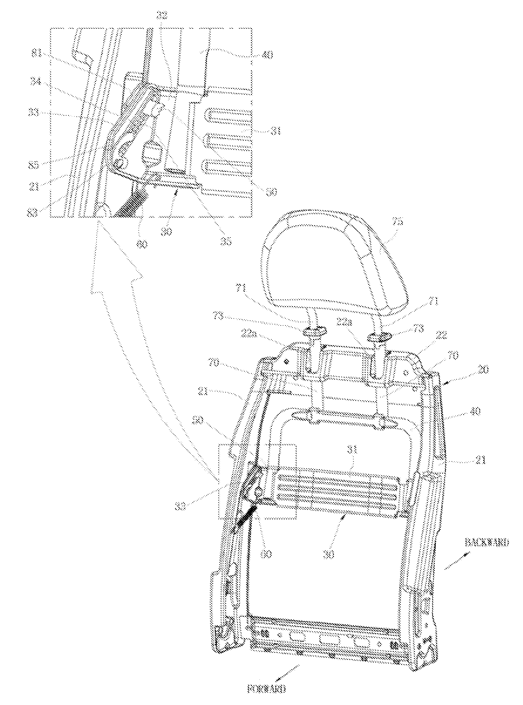
[0031]FIG. 3 illustrates an active headrest apparatus according to an embodiment of the present invention, and FIG. 4 is a perspective view of a back plate of the active headrest apparatus illustrated in FIG. 3, and FIG. 5 illustrates a state before the active headrest apparatus of FIG. 3 operates, and FIGS. 6 and 7 illustrate a state after the active headrest apparatus of FIG. 3 operates.

[0032]A vehicle seat includes a seat cushion that supports the lower body of a person who is seated in a car, a seat back that supports the upper body of the person who is seated in the car, and a headrest that is combined to a top end of the seat back so that the height of the headrest can be adjusted in a vertical direction, and that supports head and neck of the person who is seated in the car.

[0033]The framework of the seat cushion is ...


PUM


Abstract

An active headrest apparatus for a vehicle seat. A contact area in which the upper body of a person who is seated in a car in the event of a rear-end collision of the car is moved backward due to an inertial force and contacts a back plate can be increased, and a distance at which a headrest is moved and rises can be increased so that the function of an active headrest can be more faithfully performed and neck injury of the person who is seated in the car can be prevented to the maximum.

Description

CROSS-REFERENCE TO RELATED PATENT APPLICATION[0001]This application claims the benefit of Korean Patent Application No. 10-2009-0050770 filed on Jun. 9, 2009, in the Korean Intellectual Property Office, the disclosure of which is incorporated herein in its entirety by reference.BACKGROUND OF THE INVENTION[0002]1. Field of the Invention[0003]The present invention relates to an active headrest apparatus for a vehicle seat having an improved structure in which neck injury of a person who is seated in a car can be prevented to the maximum in the event of a rear-end collision of the car.[0004]2. Description of the Related Art[0005]Generally, seats for vehicles should be comfortable when a person is seated in a car and should protect the person who is seated in the car when the person has an emergency, such as a rear-end collision of the car.[0006]Seat for vehicles include a seat cushion that supports the lower body of the person who is seated in the car, a seat back that supports the upp...

Claims


Application Information

Patent Timeline
IPC IPC(8): B60N2/48
CPCB60N2/4885B60N2/888B60N2/42
Inventor LEE, JONG-YOONPARK, SANG-NAMLEE, IN-HONAM, JIN-YOUNGKIM, DO-HYUNG
Owner DYMOS
Learn More