Surface acoustic wave filter and surface acoustic wave resonator
a surface acoustic wave and filter technology, applied in piezoelectric/electrostrictive/magnetostrictive devices, piezoelectric/electrostriction/magnetostriction machines, electrical equipment, etc., can solve the problems of high temperature exposure of devices, inability to fully meet the requirements of some aspects, and insufficient trapping of surface acoustic waves in the overlap zone of electrodes, etc., to achieve the effect of improving the electric characteristics of saw devices
- Summary
- Abstract
- Description
- Claims
- Application Information
AI Technical Summary
Benefits of technology
Problems solved by technology
Method used
Image
Examples
first embodiment
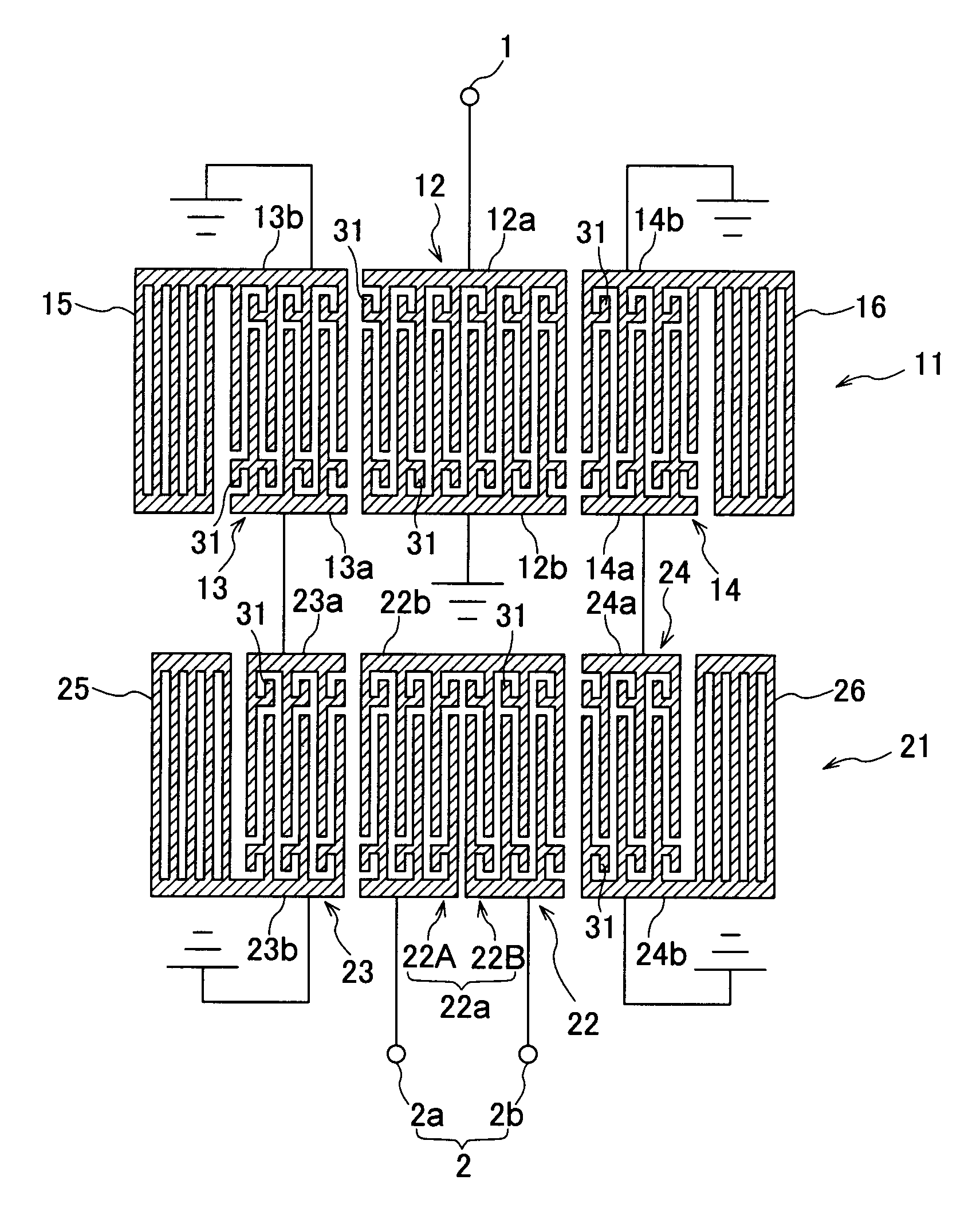
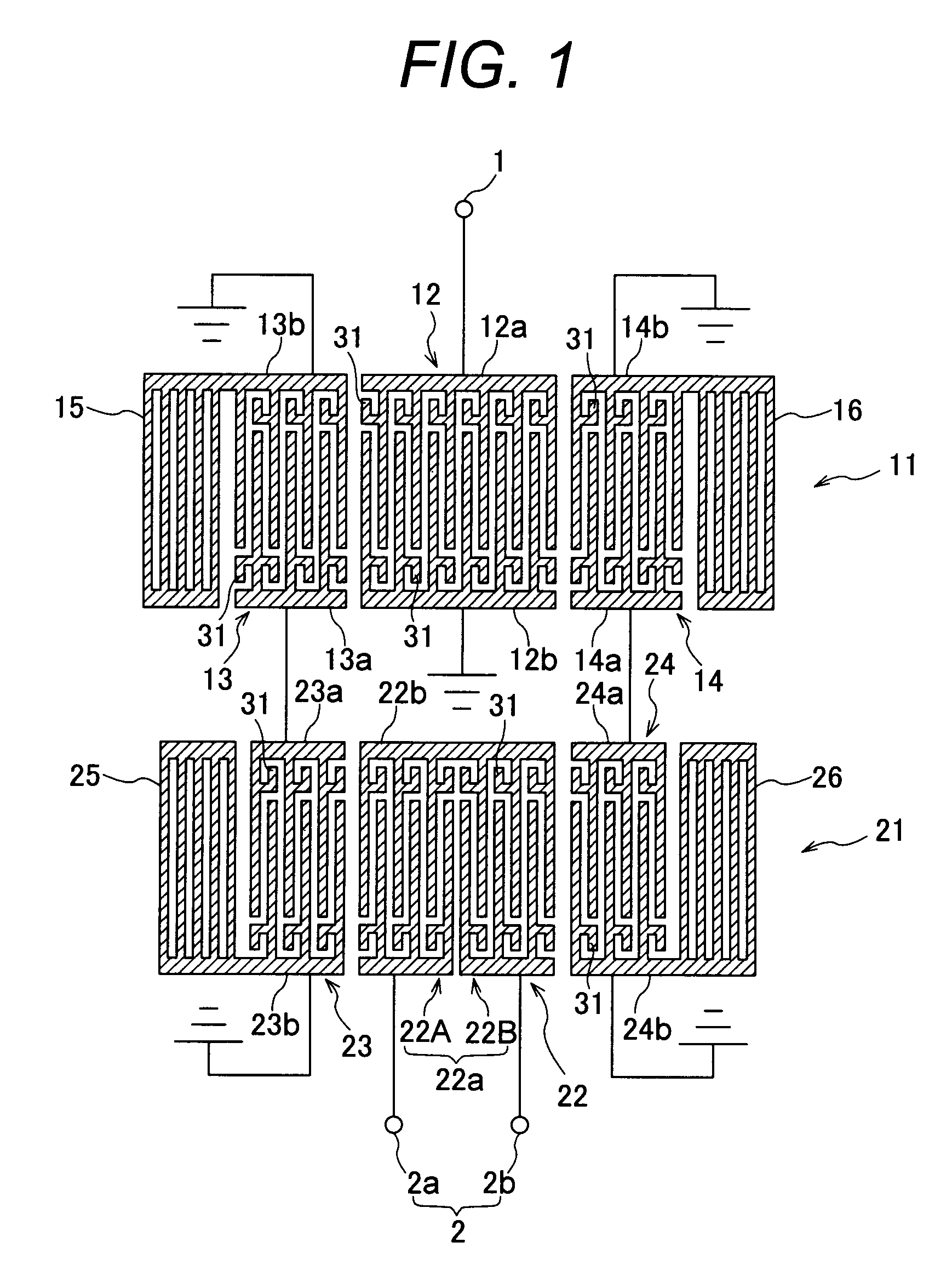
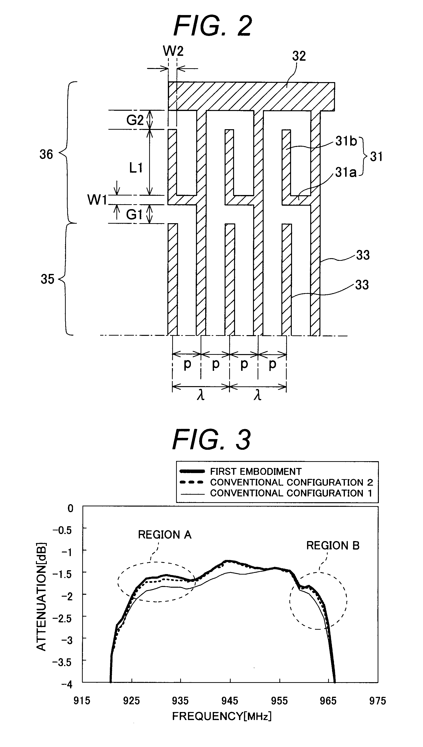
[0079]FIGS. 1 and 2 show a longitudinally coupled multi-mode SAW filter according to a first embodiment of the present invention. As shown in these figures, this SAW filter comprises two longitudinally coupled multi-mode SAW filters 11, 21 connected in series between an input terminal 1 and an output terminal 2. The SAW filter 11 at a first stage connected to the input terminal 1 comprises three IDTs 12, 13, 14 linearly arranged (in a line) and acoustically coupled in a propagation direction of surface acoustic waves; and reflectors 15, 16 disposed outside the IDTs 13, 14 on both the left and right sides. These components are formed on a piezo-electric substrate. It should be noted that in these figures (similar in other figures, later described) , the number of shown electrodes is smaller than the actual number for simplifying the illustration of each IDT and reflector.
[0080]Each IDT 12, 13, 14 which forms part of the filter 11 at the first stage comprises comb-shaped electrodes 12...
second embodiment
[0121]FIGS. 12 and 13 shows a longitudinally coupled multi-mode SAW filter according to a second embodiment. As shown in these figures, this SAW filter is similar to the filter of the first embodiment in that two longitudinally coupled multi-mode SAW filters 41, 51 are connected in series between an input terminal 1 and an output terminal 2. The configuration of IDTs 42, 43, 44, 52, 53, 54 and reflectors 45, 46, 55, 56 of each filter 41, 51, and the input / output terminals 1, 2 are basically the same as the first embodiment. While a branch electrode 61 is provided in a non-overlap zone 36 of the electrode of each IDTs 42-44, 52-54, the shape of these branch electrodes 61 is different from that in the first embodiment.
[0122]Specifically, in the first embodiment, the branch body 31b extends substantially in parallel with the interdigital electrode 33 from the leading end of the branch portion 31a toward the bus bar 32, and the branch electrode 31 generally has an L-shape, whereas in th...
third embodiment
[0125]FIG. 15 shows a longitudinally coupled multi-mode SAW filter according to a third embodiment of the present invention. As shown in FIG. 15, this SAW filter is similar to the filters of the first and second embodiments in that two longitudinally coupled multi-mode SAW filters 71, 81 are connected in series between an input terminal 1 and an output terminal 2. While the configuration of IDTs 72, 73, 74, 82, 84 and reflectors 75, 76, 85, 86 of each filter 71, 81, and the input / output terminals 1, 2 are basically the same as the first embodiment, the shape of branch electrodes 91 is different from that in the aforementioned embodiment.
[0126]Specifically, in the first and second embodiments, the leading end of the branch electrode is electrically left open, whereas in this embodiment, the leading end of the L-shaped branch electrode 91 in the first embodiment (leading end of the branch body) is connected to the bus bar 32 to electrically short-circuit the leading end of the branch ...
PUM
 Abstract
Description
Claims
Application Information
 - R&D
- Intellectual Property
- Life Sciences
- Materials
- Tech Scout
- Unparalleled Data Quality
- Higher Quality Content
- 60% Fewer Hallucinations
Browse by: Latest US Patents, China's latest patents, Technical Efficacy Thesaurus, Application Domain, Technology Topic, Popular Technical Reports.
© 2025 PatSnap. All rights reserved.Legal|Privacy policy|Modern Slavery Act Transparency Statement|Sitemap|About US| Contact US: help@patsnap.com


