System and method for detecting a breach of an electronic article surveillance tag

a technology of electronic articles and tags, applied in the field of electronic article surveillance tags, can solve the problems of easy misplacement of separate tacks, unnecessary frustration for users, replacement costs, etc., and achieve the effect of substantially equivalent cross-sectional profiles and convenient threading of lanyards

Active Publication Date: 2010-12-09
SENSORMATIC ELECTRONICS CORP
View PDF4 Cites 26 Cited by
  • Summary
  • Abstract
  • Description
  • Claims
  • Application Information

AI Technical Summary

Benefits of technology

[0013]According to another embodiment, an electronic article surveillance (EAS) tag is provided and includes a tag body that defines an interior having an opening that leads into the interior of the tag body and a lanyard mounting structure that is coupled to the tag body. The securing device includes a lanyard having a first end and a second end opposite the first end. The first end is coupled to the lanyard mounting structure in the tag body interior. The securing device further includes a fastener that is coupled to the second end of the lanyard and a pin assembly that is coupled to the fastener. The lanyard, the fastener and the pin assembly have substantially equivalent cross-sectional profiles. The substantially equivalent cross-sectional profiles facilitate threading the lanyard, the fastener and the pin assembly through small openings.

Problems solved by technology

The separate tacks are easily misplaced, which causes unnecessary frustration to users and replacement costs.

Method used


Image

  • System and method for detecting a breach of an electronic article surveillance tag
  • System and method for detecting a breach of an electronic article surveillance tag
  • System and method for detecting a breach of an electronic article surveillance tag

Examples


Embodiment Construction

[0026]Before describing in detail exemplary embodiments that are in accordance with the present invention, it is noted that like reference designators refer to like elements. Referring now to the figures, as used herein, relational terms, such as “first” and “second,”“top” and “bottom,” and the like, may be used solely to distinguish one entity or element from another entity or element without necessarily requiring or implying any physical or logical relationship or order between such entities or elements. The terms “upper” and “lower” refer only to the orientation of the EAS tag and are not structural limitations.

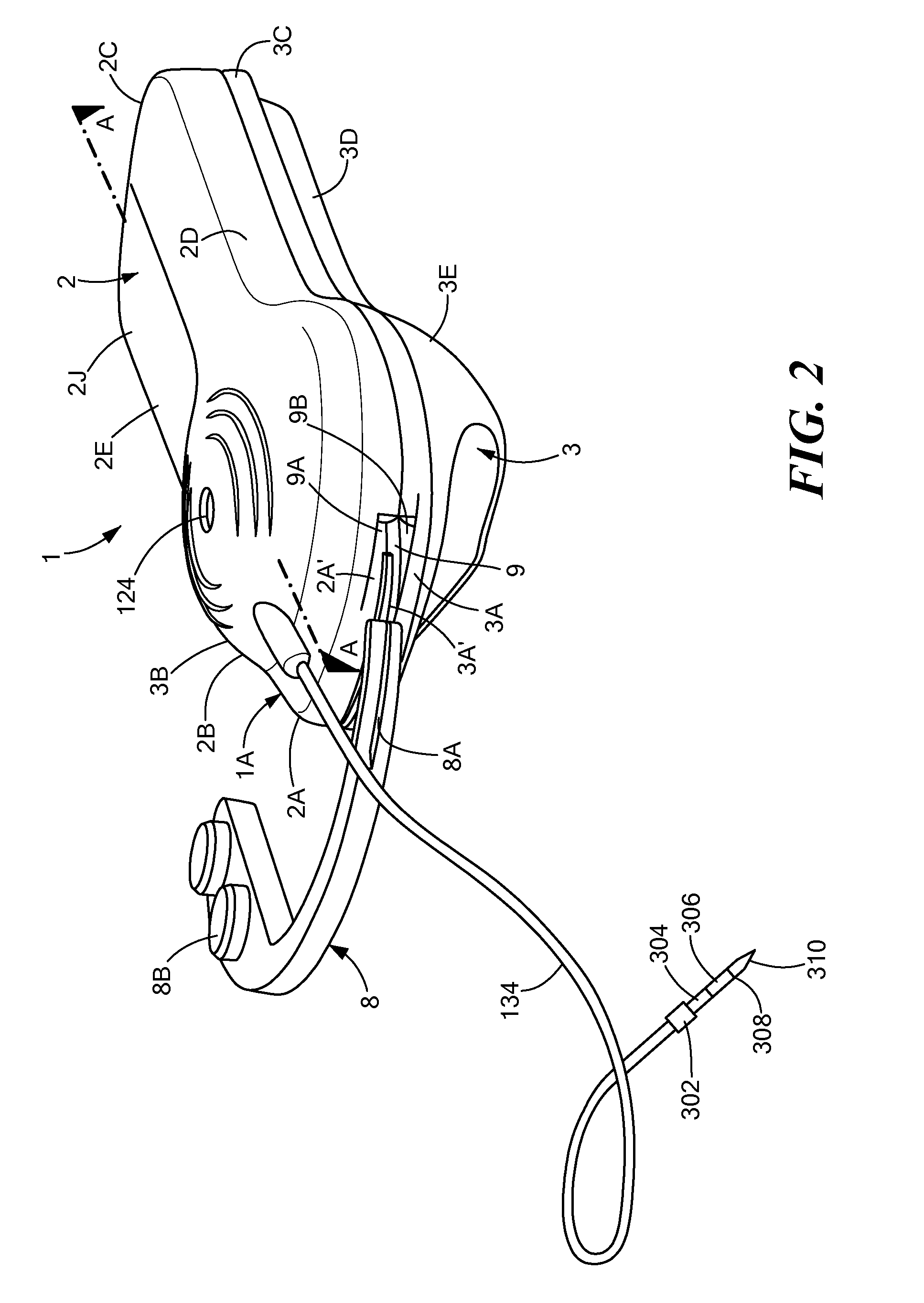
[0027]FIG. 2 illustrates a tag 1 that includes an upper housing 2 having side walls 2A, 2B, 2C and 2D that are joined by a top wall 2E. The EAS tag 1 also includes a lower housing 3 having side walls 3A, 3B, 3C and 3D that are joined by a bottom wall 3E. The upper and lower housings 2 and 3 are joined or mated along corresponding or associated side wall pairs (2A, 3A), (2B...


PUM


Abstract

An EAS tag is provided having improved anti-defeat devices and methods. A pin assembly is coupled to a lanyard and includes a reduced cross-sectional profile that may be passed through a monitored article to produce no damage or minimal damage to the monitored article. The pin assembly engages a spring clamp provided in the EAS tag and is electrically coupled to an intermediate spring contact that provides an electrical current to a PC board for arming the EAS tag. A force may be applied to the intermediate spring contact to generate a reset signal that disarms the EAS tag. An alarm signal is generated if current to the PC board is disrupted without a corresponding reset signal, such as if the pin assembly is removed without rotating the intermediate spring contact or if the lanyard is cut. The tag body is provided with an arcuate channel through which an arcuate detacher probe can be guided for releasing the attaching assembly part.

Description

CROSS-REFERENCE TO RELATED APPLICATION[0001]n / aSTATEMENT REGARDING FEDERALLY SPONSORED RESEARCH OR DEVELOPMENT[0002]n / aFIELD OF THE INVENTION[0003]This invention relates to electronic article surveillance (“EAS”) tags, and in particular to EAS tags having anti-defeat mechanisms.BACKGROUND OF THE INVENTION[0004]Electronic article surveillance systems are used for inventory control and to prevent theft or unauthorized removal of articles from a controlled area. The EAS systems include transmitters, receivers, and EAS tags. Typically, the transmitters and the receivers are positioned at entry / exit points of the controlled area and the EAS tags are affixed to articles that are located within the controlled area. The EAS tags include a marker or a sensor that receives the transmitter signals and generates a response signal that is detected by the receiver. The EAS system generates an alert signal when the response signal is detected within a predefined distance of the receiver.[0005]A va...

Claims


Application Information

Patent Timeline
Patent Type & Authority Applications(United States)
IPC IPC(8): G08B13/14
CPCE05B73/0017E05B73/0005
Inventor HESCH, JR., JOHNDICARLO, EDWARD J.FORD, JOHN C.
Owner SENSORMATIC ELECTRONICS CORP
Why Eureka
Try Eureka