
Head mounted 3D display

a 3d display and display head technology, applied in the direction of cathode-ray tube indicators, optics, sport apparatus, etc., can solve the problems of virtual image display in augmented reality systems, and achieve the effect of reducing motion sickness and fatigu

Inactive Publication Date: 2010-12-09
SIROCCO VISION
View PDF10 Cites 147 Cited by
  • Summary
  • Abstract
  • Description
  • Claims
  • Application Information

AI Technical Summary

Benefits of technology

[0003]The present invention seeks to provide a head mounted display (HMD) that augments reality (the see-through effect), as is described more in detail hereinbelow. The HMD provides a three-dimensional sensation wherein the foreground virtual image is seen by one eye and the real surrounding is seen by both eyes, thereby reducing the motion sickness and the fatigue generated by two image 3D displays of the prior art.
[0004]The “see-through” effect combines the virtual image at one focus and the real world perceived by each eye, with each eye having a slightly different view of the reality perception. Both eyes have see-through screens to provide similar surroundings (providing a reality view with its 3D information), thereby avoiding a mismatch between the eyes. One cannot project a virtual image on one eye and have the surroundings seen by both eyes when there is a significant difference in brightness between the two screens (e.g., 20% difference in brightness).

Problems solved by technology

A problem may occur with displays of virtual images in augmented reality systems.
The problem is that of “virtual reality” sickness, which can be experienced by users of video games or flight simulators.
It is believed that the source of the problem is a sensory mismatch that causes motion sickness, which is the sensation the brain encounters when it perceives that the body is in motion (when in fact there is no motion), and it attempts to correct bodily posture to counteract the perceived physical sensation.
Another example of sensory mismatch occurs when the eye perceives motion, but no motion actually occurs.

Method used


Image

  • Head mounted 3D display
  • Head mounted 3D display
  • Head mounted 3D display

Examples


Embodiment Construction

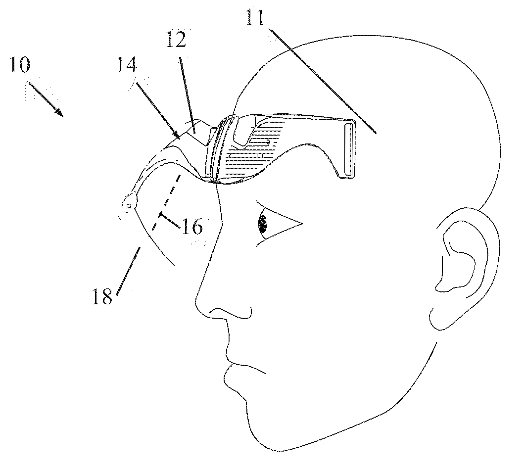
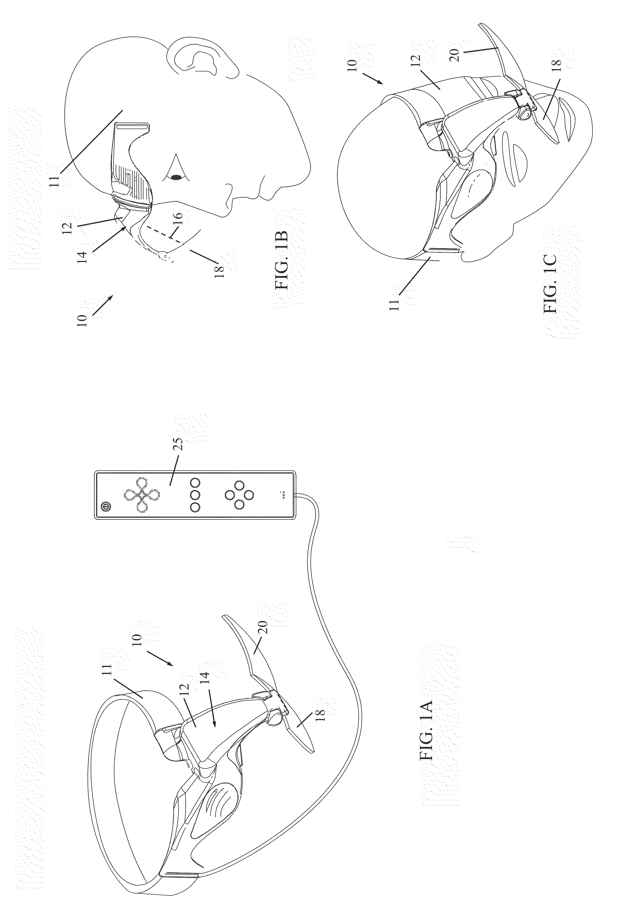
[0021]Reference is now made to FIGS. 1A-C, which illustrates a HMD 10, constructed and operative in accordance with a non-limiting embodiment of the present invention.

[0022]HMD 10 includes a headband 11 with a housing 12 mounted thereon, and an optics module 14 disposed in housing 12. Optics module 14 will be described more in detail below with reference to FIG. 3. Optics module 14 may include a computer-generated imagery (CGI) system and suitable optical elements (lenses, mirrors, filters, LCD, OLED, etc.) for generating images and projecting a beam 16 of the images on a display substrate (also called display screen) 18 pivotally attached to housing 12. It is noted that optics module 14 may include the display screen; the module has the optical power capacity to generate the virtual image. It may be spheric or aspheric.

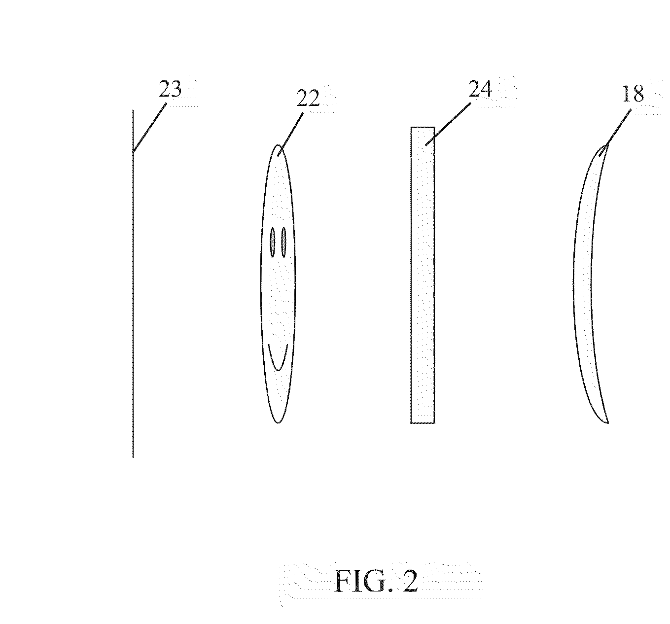
[0023]A non-display screen 20 is also pivotally attached to housing 12. The images 22 displayed on display screen 18 are displayed at a certain focal distance from H...


PUM


Abstract

A head mounted display (HMD) including a display screen attached to a housing and aligned to be in a line of sight of a first eye of a user, an optics module disposed in the housing, for generating an image and projecting a beam of the image on the display screen, and a non-display screen attached to the housing and aligned to be in a line of sight of a second eye of the user, wherein the image displayed on the display screen is displayed at a virtual display distance different than a distance at which an image of the non-display screen is perceived.

Description

FIELD OF THE INVENTION[0001]The present invention relates generally to head mounted displays, and particularly to a see-through augmented reality head mounted display which gives the effect of a three-dimensional virtual image superimposed on the real world.BACKGROUND OF THE INVENTION[0002]A head mounted display system is a display system that is mounted on a user's head and projects a virtual image for one or both eyes. Head mounted displays have many uses, such as in games, just to name one. A commonly used method to provide a three-dimensional virtual image is to project two images generated from different perspectives to each eye to mimic a real situational 3D screen. The displays require two image screens with separate images. The 3D effect is sensed by the brain by combining several clues, including the difference (parallax) between the two images, the focus of the image, and other clues such as known size, shading, perspective, etc. A problem may occur with displays of virtua...

Claims


Application Information

Patent Timeline
Patent Type & Authority Applications(United States)
IPC IPC(8): G09G5/00
CPCA63F13/02A63F2300/301G02B27/0093G02B27/0172G02B27/2228G02B2027/0127G09G2380/02G02B2027/0154G06F3/012G06F3/0346G06F3/147G09G3/003G09G5/00G02B2027/0138A63F2300/203A63F2300/8082A63F13/211A63F13/213A63F13/245A63F13/26A63F13/428A63F13/5255A63F13/53A63F13/98G02B30/34G09G3/035A63F13/25
Inventor RAVIV, RONIGANOR, LIRAN
Owner SIROCCO VISION
Learn More