Projection zoom lens and projection-type display apparatus

Active Publication Date: 2010-12-09
FUJIFILM CORP
View PDF4 Cites 13 Cited by
  • Summary
  • Abstract
  • Description
  • Claims
  • Application Information

AI Technical Summary

Benefits of technology

[0039]Specifically, the projection zoom lens according to the embodiment of the invention has the following advantages by making the powers of the first and second lens groups be negative. The negative powers can be distributed to the two lens groups, and it is possible to decrease the negative power of the first lens group. As a result, it is possible to suppress the fluctuation in aberration caused by the focusing. Besides, this configuration is advantageous in correction of off-axis aberrations such as comatic aberration and image field curvature.
[0040]Further, in the arrangement area of the second lens group, the off-axis rays pass through relatively high position. As a result

Problems solved by technology

However, in the description disclosed in JP-A-2005-62226, since astigmatism is too large, when a high-resolution light valve is used, there is a problem in that aberration c

Method used


Image

  • Projection zoom lens and projection-type display apparatus
  • Projection zoom lens and projection-type display apparatus
  • Projection zoom lens and projection-type display apparatus

Examples


Example

Example 1

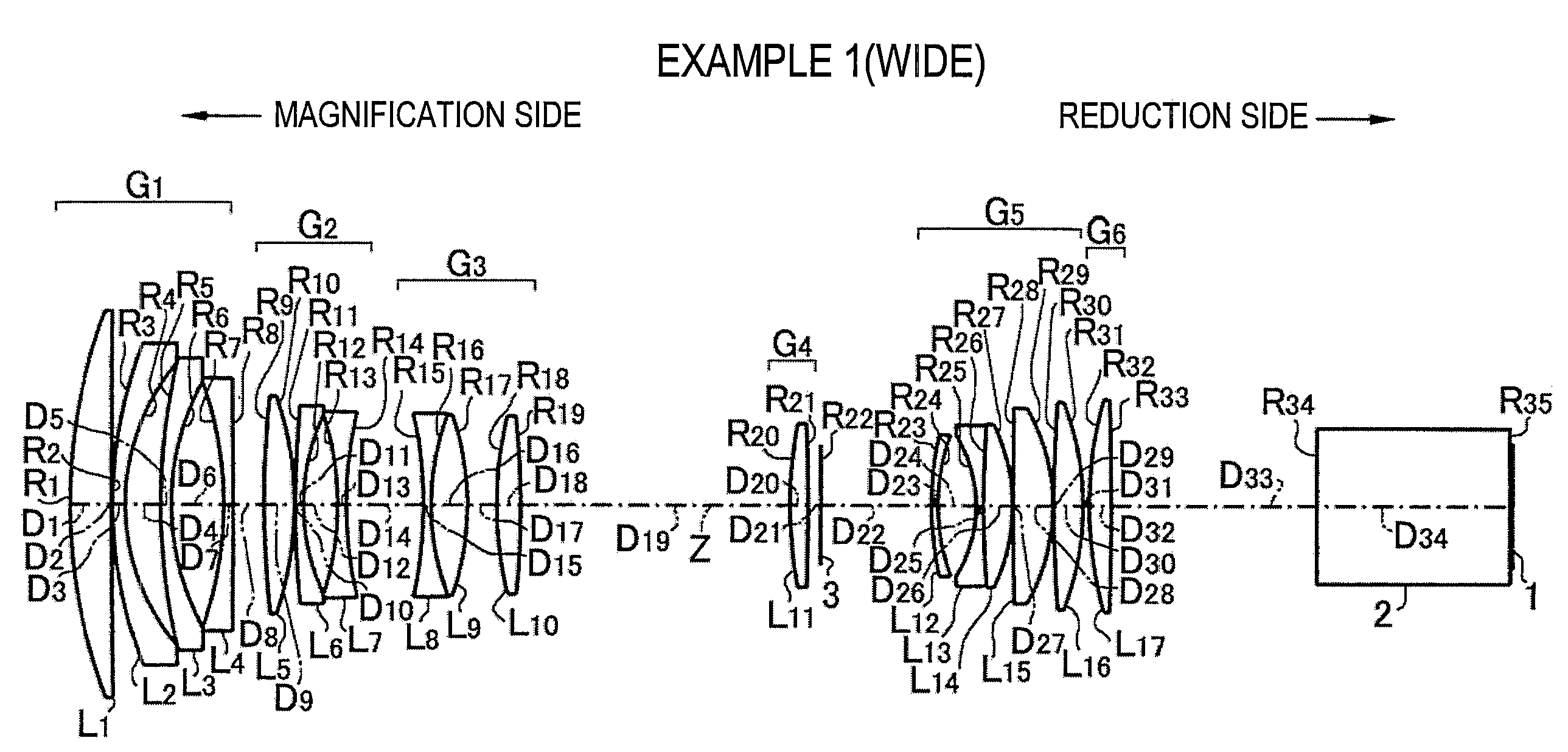
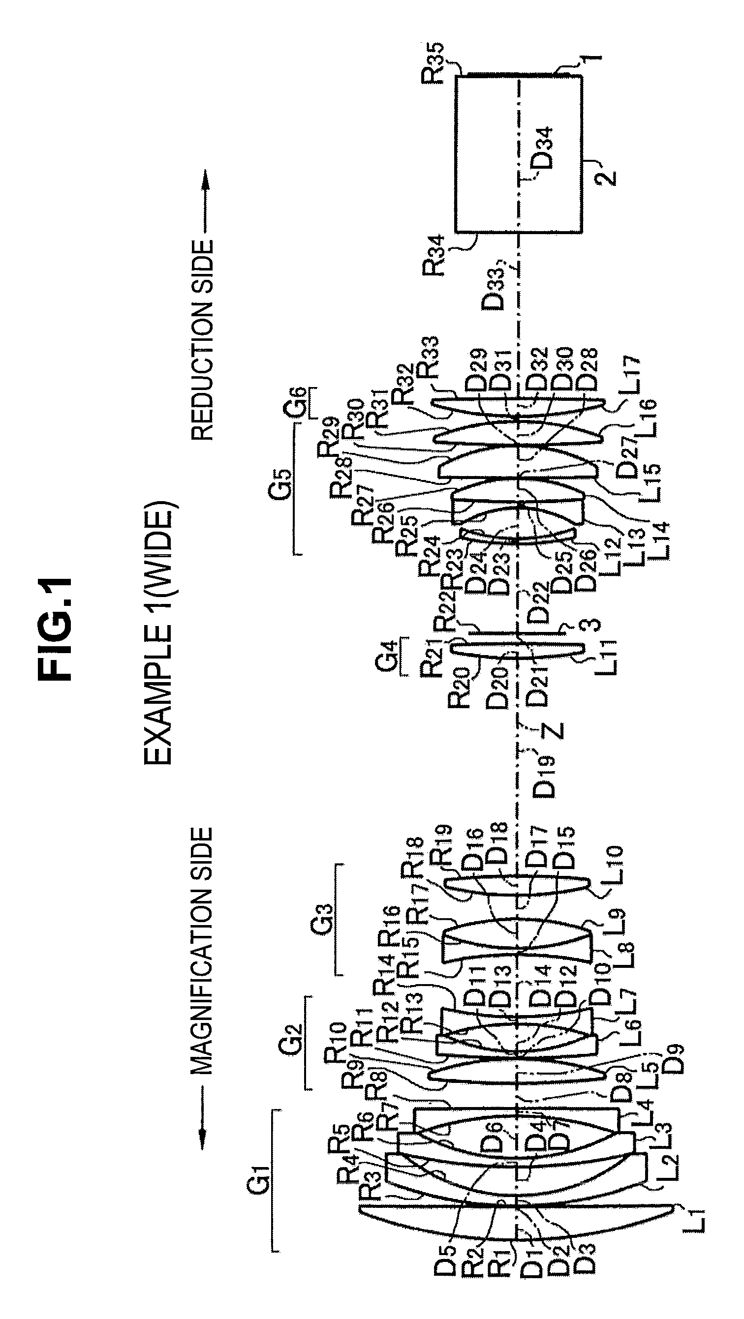
[0088]The projection zoom lens system according to Example 1 has a configuration shown in FIG. 1 as described above. Specifically, in the lens, the first lens group G1 includes, in order from the magnification side: the first lens L1 formed as a positive meniscus lens convex toward the magnification side; the second lens L2 formed as a negative meniscus lens convex toward the magnification side; the third lens L3 formed as a negative meniscus lens convex toward the magnification side; and the fourth lens L4 formed as a negative meniscus lens convex toward the reduction side. The second lens group G2 includes, in order from the magnification side: the fifth lens L5 formed as a biconvex lens; the sixth lens L6 formed as a negative meniscus lens convex toward the magnification side; and the seventh lens L7 formed as a biconcave lens.

[0089]Further, the third lens group G3 includes, in order from the magnification side: the eighth lens L8 formed as a biconcave lens; the ninth le...

Example

Example 2

[0103]FIG. 3 shows a schematic configuration of the projection zoom lens according to Example 2. The projection zoom lens has a six-group configuration substantially the same as that of Example 1. However, the projection zoom lens is different in that the fifteenth lens L15 constituting the fifth lens group G5 is formed as a positive meniscus lens convex toward the reduction side.

[0104]FIG. 4 shows moved positions of the lens groups at the wide-angle end (WIDE) and the telephoto end (TELE) in the projection zoom lens according to Example 2.

[0105]As shown in FIG. 4, during zooming, the first lens group G1, the second lens group G2, and the sixth lens group G6 are formed as fixed groups, and the third to fifth lens group G3 to G5 are formed as movable groups.

[0106]Further, the aperture (the variable aperture stop) 3 is disposed between the fourth lens group G4 and the fifth lens group G5. During zooming from the wide-angle end to the telephoto end, the aperture is moved from ...

Example

Example 3

[0115]FIG. 5 shows a schematic configuration of the projection zoom lens according to Example 3. The projection zoom lens has a six-group configuration substantially the same as that of Example 1. However, the projection zoom lens is different in the following points. First, the fourth lens L4 constituting the first lens group G1 is formed as a biconcave lens. Second, the third lens group G3 includes, in order from the magnification side: the eighth lens L8 formed as a negative meniscus lens convex toward the magnification side; and the ninth lens L9 formed as a biconvex lens. Third, the sixteenth lens L16 constituting the sixth lens group G6 is formed as a piano-convex lens convex toward the magnification side. Furthermore, the fourth lens group G4 includes only the tenth lens L10, and the fifth lens group G5 includes the five lenses L11 to L15

[0116]FIG. 6 shows moved positions of the lens groups at the wide-angle end (WIDE) and the telephoto end (TELE) in the projection ...


PUM


Abstract

A projection zoom lens projects an optical image of rays, which are irradiated from a light source onto a light valve and are modulated by a predetermined image displayed on the light valve, onto a screen. The projection zoom lens includes a plurality of lens groups that is formed as a telecentric system on the reduction side thereof and includes at least two movable lens groups which are movable during zooming. In the projection zoom lens, the plurality of lens groups is arranged to include, in order from a magnification side, at least a first lens group and a second lens group. The first lens group has a negative refractive power, remains stationary during zooming, and performs focusing. The second lens group has a negative refractive power and remains stationary during zooming and focusing.

Description

CROSS-REFERENCE TO RELATED APPLICATIONS[0001]This application is based upon and claims the benefit of priority from the Japanese Patent Application No. 2009-137514 filed on Jun. 8, 2009; the entire contents of which are incorporated herein by reference.BACKGROUND OF THE INVENTION[0002]1. Field of the Invention[0003]The present invention relates to a projection zoom lens provided in projection-type display apparatuses and the like and a projection-type display apparatus equipped with the projection zoom lens.[0004]2. Description of the Related Art[0005]In recent years, projection-type display apparatuses, which use various light valves such as transmissive and reflective liquid crystal display apparatuses and DMD display apparatuses and have a relatively long back focal length, have come into widespread use, and have been improved in performance.[0006]Such high-performance projection-type display apparatuses employ a configuration using three reflective liquid crystal display devices...

Claims


Application Information

Patent Timeline
IPC IPC(8): G02B15/177
CPCG03B21/14G02B15/177G03B21/142G02B15/1465
Inventor AMANO, MASARU
Owner FUJIFILM CORP
Why Eureka
Try Eureka