LED lighting fixture

a technology of led lighting fixtures and led lamps, which is applied in the direction of lighting and heating devices, semiconductor devices for light sources, lighting support devices, etc., can solve the problems of overheating of the light apparatus with the conventional lamp, short life of the conventional light apparatus, and high light intensity and low power consumption, so as to enhance the efficiency of heat transfer and efficiently remove the heat generated by the led

Inactive Publication Date: 2010-12-09
ZHENG JIN SONG
View PDF4 Cites 27 Cited by
  • Summary
  • Abstract
  • Description
  • Claims
  • Application Information

AI Technical Summary

Benefits of technology

[0012]A main object of the present invention is to provide a LED light fixture, which is able to ef

Problems solved by technology

The overheated of the light apparatus with the conventional lamp is one of the reasons of the short life of conventional light apparatus.
Currently, LED is gradually replacing the conventional light source, since the LED is known as its high light intensity and low power consuming.
If the heat can not be efficiently dissipated, it may decrease the stability for normally performing the LED due to the damage of the driven circuit required to drive the LED.
The fail of dissipating heat properly may also affect the light output and shorten the long life and durability of LED.
However, the protruded fins of LED apparatus has the drawbacks of installing the LED apparatus with other object or surfaces, such as a wall, a corner, or in the closet due to its uneven surface of the protruding fins.
Furthermore, the heat conductive material of the fins may has free electrons generated from the current or the driven circuit of LED and distributed on the surface of fins, so that the protruding fins may easily to accumulate dust thereon, so as to decrease the efficiency of

Method used


Image

  • LED lighting fixture
  • LED lighting fixture
  • LED lighting fixture

Examples


Embodiment Construction

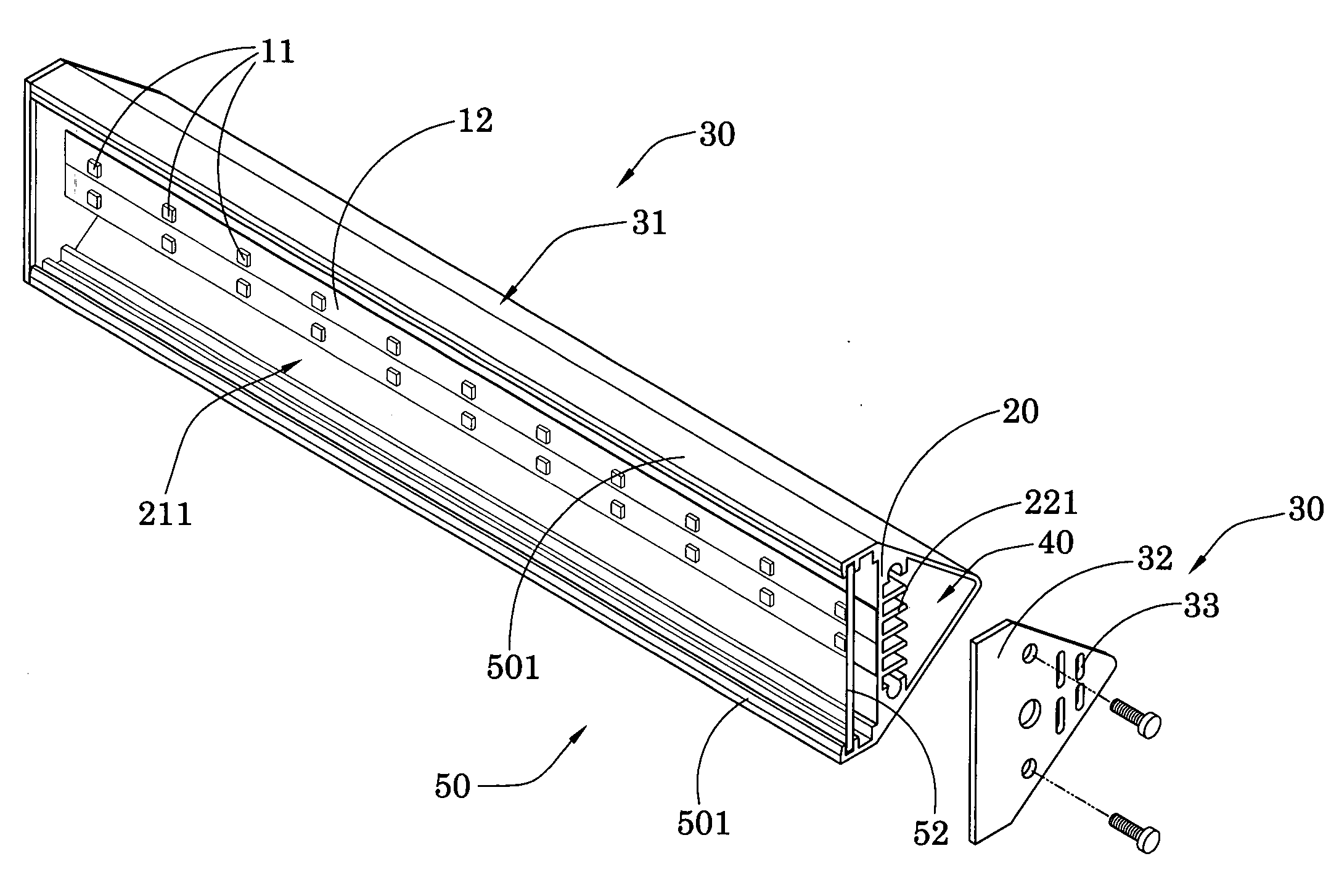
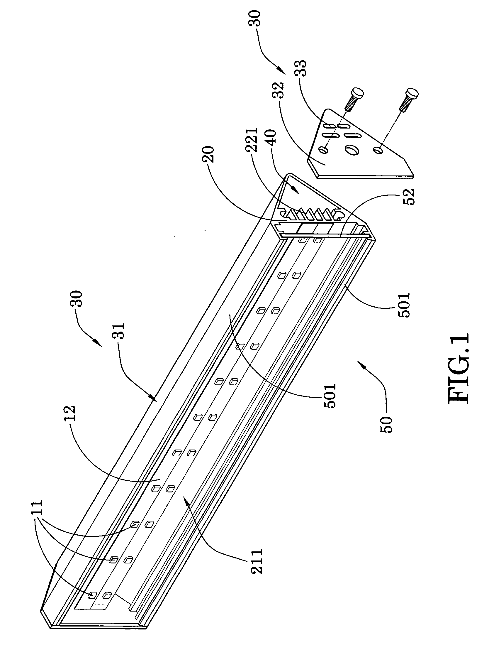
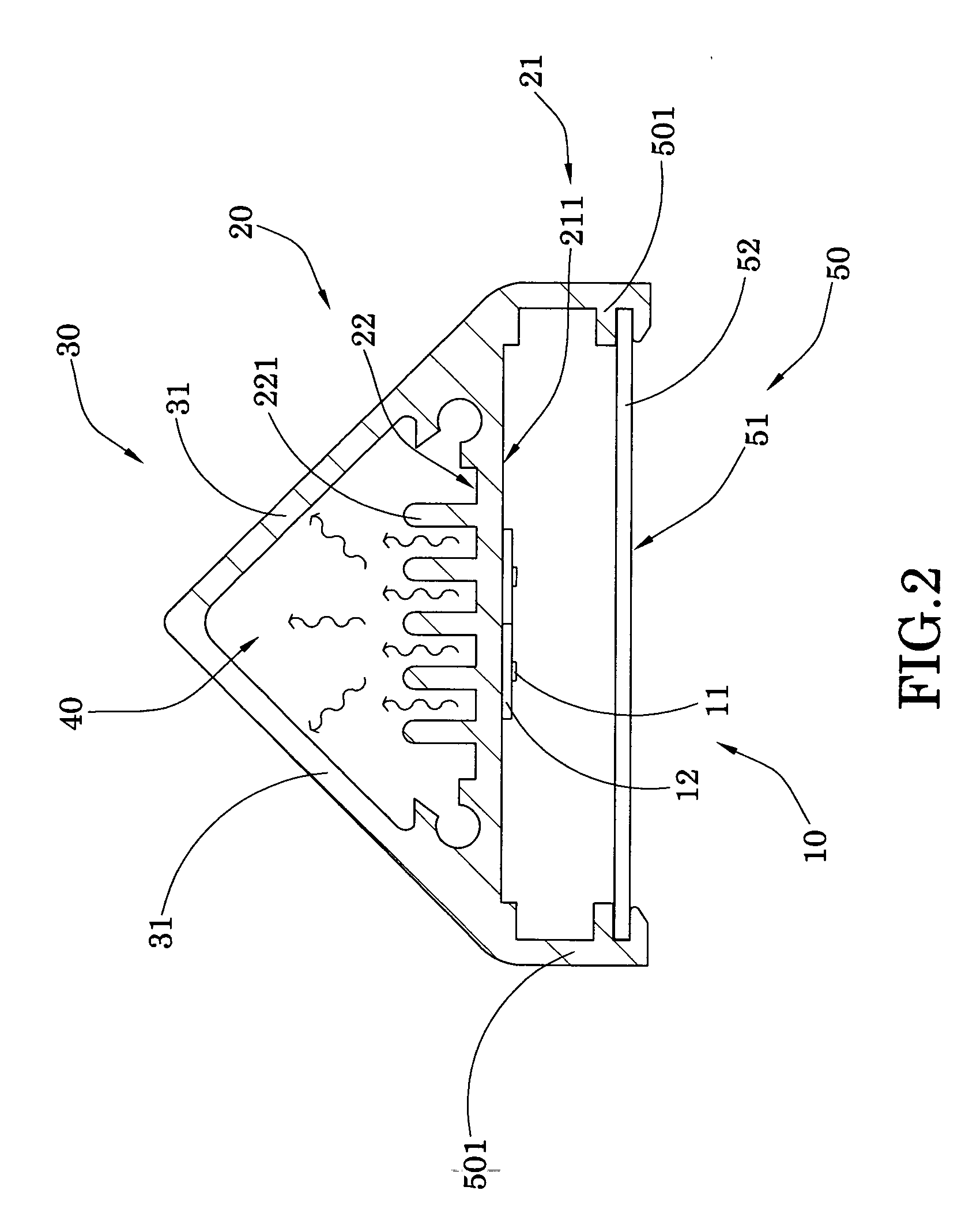
[0027]Referring to FIGS. 1 to 3 of the drawings, a LED light fixture according to a preferred embodiment of the present invention is illustrated, wherein the LED light fixture comprises a LED light arrangement 10 and a supporting frame for supporting the LED light arrangement 10. The LED light arrangement 10 comprises one or more diodes 11 as a light source, and a circuit layer 12 electrically connected to each of the diodes 11 for operatively controlling the LED light performance.

[0028]The supporting frame, which is made of heat conductive material, comprises a heat transmitting wall 20 having a first side 21 and a second side 22, wherein the first side 21 is for supporting the LED light arrangement 10 thereon, and the second side defines a heat transferring chamber 40 thereat in a concealed manner for containing gaseous in the heat transferring chamber 40. Therefore, the heat transmitting wall 20 is arranged for conductively transferring heat from the diodes 11 at the first side 2...


PUM


Abstract

A LED lighting fixture includes a LED light arrangement and a supporting frame for supporting the LED light arrangement. The LED light arrangement includes one or more diodes and a circuit layer for operatively driving the diodes. The supporting frame includes a heat transmitting wall having a first side for supporting the LED light arrangement thereon and a second side to define a heat transferring chamber thereat in a concealed manner, and a concealing frame extended from the transmitting wall to form the heat transferring chamber therewithin. A plurality of heat transmitting fins further protrudes out from the second side to enlarge the heat conduction area, so as to enhance the heat conductive transferring rate. The heat transmitting fins are concealed within the heat chamber via the concealing frame, so that the overall size and outer structure of the LED lighting fixture is remaining the same.

Description

BACKGROUND OF THE PRESENT INVENTION[0001]1. Field of Invention[0002]The present invention relates to a light fixture, and more specifically relates to a LED light fixture, which has a supporting frame for supporting a LED light arrangement and for dissipating the heat generated from the LED light arrangement to exterior, so as to minimize the overall size and remain the outer smooth surface of the LED lighting fixture.[0003]2. Description of Related Arts[0004]The conventional lamp, in order to generate the higher light intensity for illuminating the environment, usually accumulates considerable heat energy from the lamp of light source. The overheated of the light apparatus with the conventional lamp is one of the reasons of the short life of conventional light apparatus.[0005]Currently, LED is gradually replacing the conventional light source, since the LED is known as its high light intensity and low power consuming. LEDs are also efficient in that they produce more lumens per wat...

Claims


Application Information

Patent Timeline
IPC IPC(8): F21V1/00F21S4/00F21V29/00
CPCF21V29/004F21V29/763F21Y2103/003F21Y2101/02F21V1/02F21Y2103/10F21Y2115/10
Inventor ZHENG, JIN SONG
Owner ZHENG JIN SONG
Why Eureka
Try Eureka