
Rotation switch and electronic timepiece

a technology of rotating switch and electronic timepiece, which is applied in the direction of electric winding, instruments, and horology, can solve the problems of increasing the overall device size, and achieve the effects of reducing the thickness and the overall switch size, accurate detection of magnetic field, and high sensitivity

Active Publication Date: 2010-12-09
CASIO COMPUTER CO LTD
View PDF8 Cites 24 Cited by
  • Summary
  • Abstract
  • Description
  • Claims
  • Application Information

AI Technical Summary

Benefits of technology

[0009]The present invention has been conceived to solve the above-described problems. An object of the present invention is to reduce the thickness and the size of the overall switch and provide a rotation switch of which the magnetic sensor accurately detects the magnetic field of the rotating magnet with high sensitivity, without being affected by external magnetic fields.

Problems solved by technology

Therefore, the magnetic sensor is easily affected by magnetic fields outside of the wristwatch, which possibly leads to malfunction.
However, there is a problem in that, when the magnet is designed larger, the thickness of the overall device increases, causing the increase of the overall device size.

Method used


Image

  • Rotation switch and electronic timepiece
  • Rotation switch and electronic timepiece
  • Rotation switch and electronic timepiece

Examples


Embodiment Construction

[0028]The present invention will hereinafter be described in detail with reference to the preferred embodiments shown in the accompanying drawings.

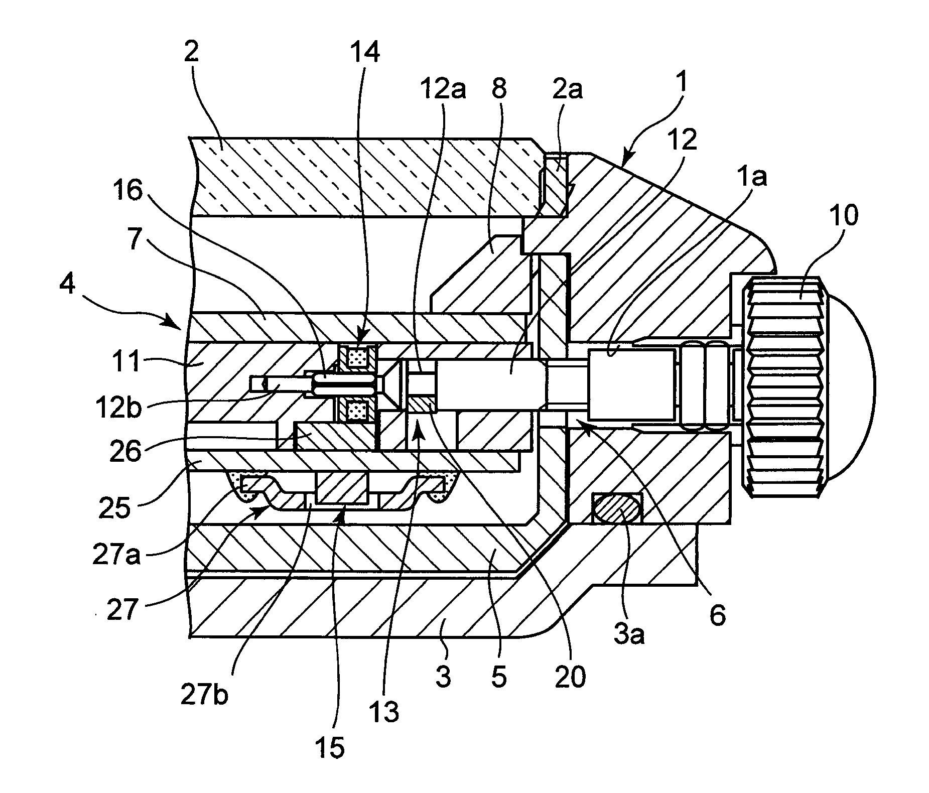
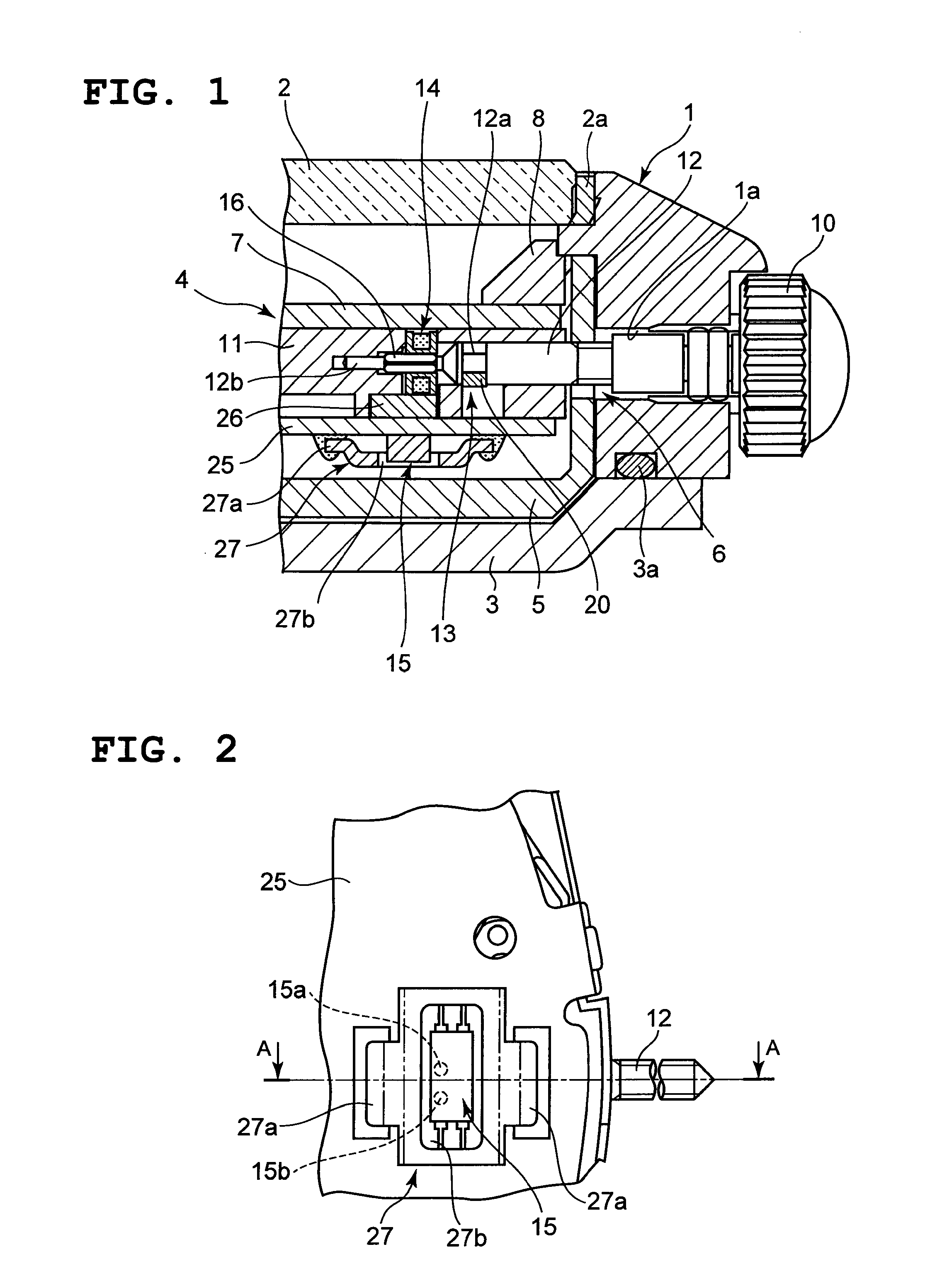
[0029]As shown in FIG. 1, an electronic wristwatch includes a wristwatch case 1. A watch crystal 2 is attached to the upper opening section of this wristwatch case 1 by a gasket 2a, and a case back 3 is attached to the bottom section of the wristwatch case 1 by a water-proof ring 3a.

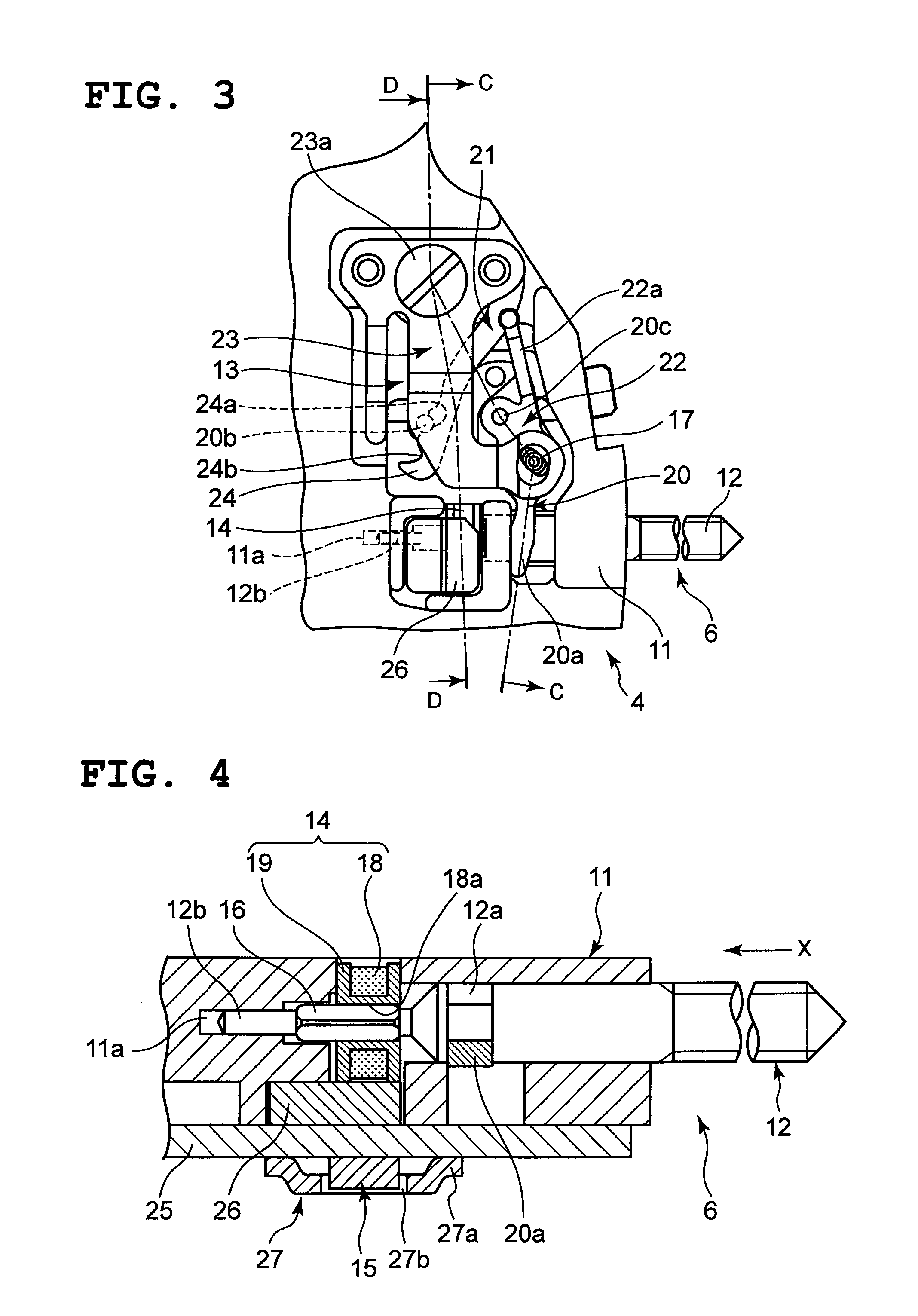
[0030]Also, as shown in FIG. 1, a timepiece module 4 is provided inside the wristwatch case 1 by a casing ring 5, and as shown in FIG. 1 and FIG. 2, a timepiece movement (not shown) that moves the hands and a time adjusting device 6 that is used for time adjustment are included in this timepiece module 4. In this instance, a dial 7 is provided on the top surface of the timepiece module 4, and a ring-shaped panel member 8 is provided on the top surface of this dial 7.

[0031]In addition, as shown in FIG. 1, the time adjusting device 6 includes a crown 10, a stem...


PUM


Abstract

A rotation switch includes an operating member that is operable to rotate, a magnet member that rotates integrally with the operating member, a magnetic sensor that is placed opposite to the magnet member, and a frame-shaped anti-magnetic shield plate that surrounds the periphery of the magnetic sensor.

Description

CROSS-REFERENCE TO RELATED APPLICATION[0001]This application is based upon and claims the benefit of priority from the prior Japanese Patent Application No. 2009-138159, filed Jun. 9, 2009, the entire contents of which is incorporated herein by reference.BACKGROUND OF THE INVENTION[0002]1. Field of the Invention[0003]The present invention relates to a rotation switch and an electronic timepiece.[0004]2. Description of the Related Art[0005]An electronic wristwatch, for example, is configured such that the stem is pulled outward to a predetermined position and rotated so that the hands thereof move corresponding to the rotation of the stem for time adjustment. As a time adjusting device for an electronic wristwatch such as this, a device configured as described in United States Patent Application. Publication No. 2008 / 0112275 is known in which the wristwatch case is provided with a stem that is movable to a first position and a second position in an axial direction thereof and rotatab...

Claims


Application Information

Patent Timeline
IPC IPC(8): G04B43/00G01B7/30
CPCG04C3/004H01H36/0006H01H25/06H01H19/00
Inventor KIMURA, SOHMACHIDA, SYUUICHI
Owner CASIO COMPUTER CO LTD
Learn More