X-ray Apparatus

a technology of x-ray tube and x-ray tube, which is applied in the direction of x-ray tube target, x-ray tube convertor, therapy, etc., can solve the problem of unnecessary destruction of healthy cells of patients

Active Publication Date: 2010-12-09
ELEKTA AB +1
View PDF4 Cites 27 Cited by
  • Summary
  • Abstract
  • Description
  • Claims
  • Application Information

AI Technical Summary

Benefits of technology

[0008]In this way, the target can move so that a different part is exposed to the electron beam when different pulses arrive. This enables the appropriate target material to be employed depending on the selected energy.
[0012]Alternatively, or in addition, the target can have inhomogeneities in its thickness to cater for the different electron energies. Thickness differences may cause interesting weight distributions (depending on their spatial distribution), which could be balanced by partially, fully or over-filling the thinner areas with an inert material.

Problems solved by technology

Failure to do so may result in the unnecessary destruction of healthy cells of the patient.

Method used


Image

  • X-ray Apparatus
  • X-ray Apparatus
  • X-ray Apparatus

Examples


Embodiment Construction

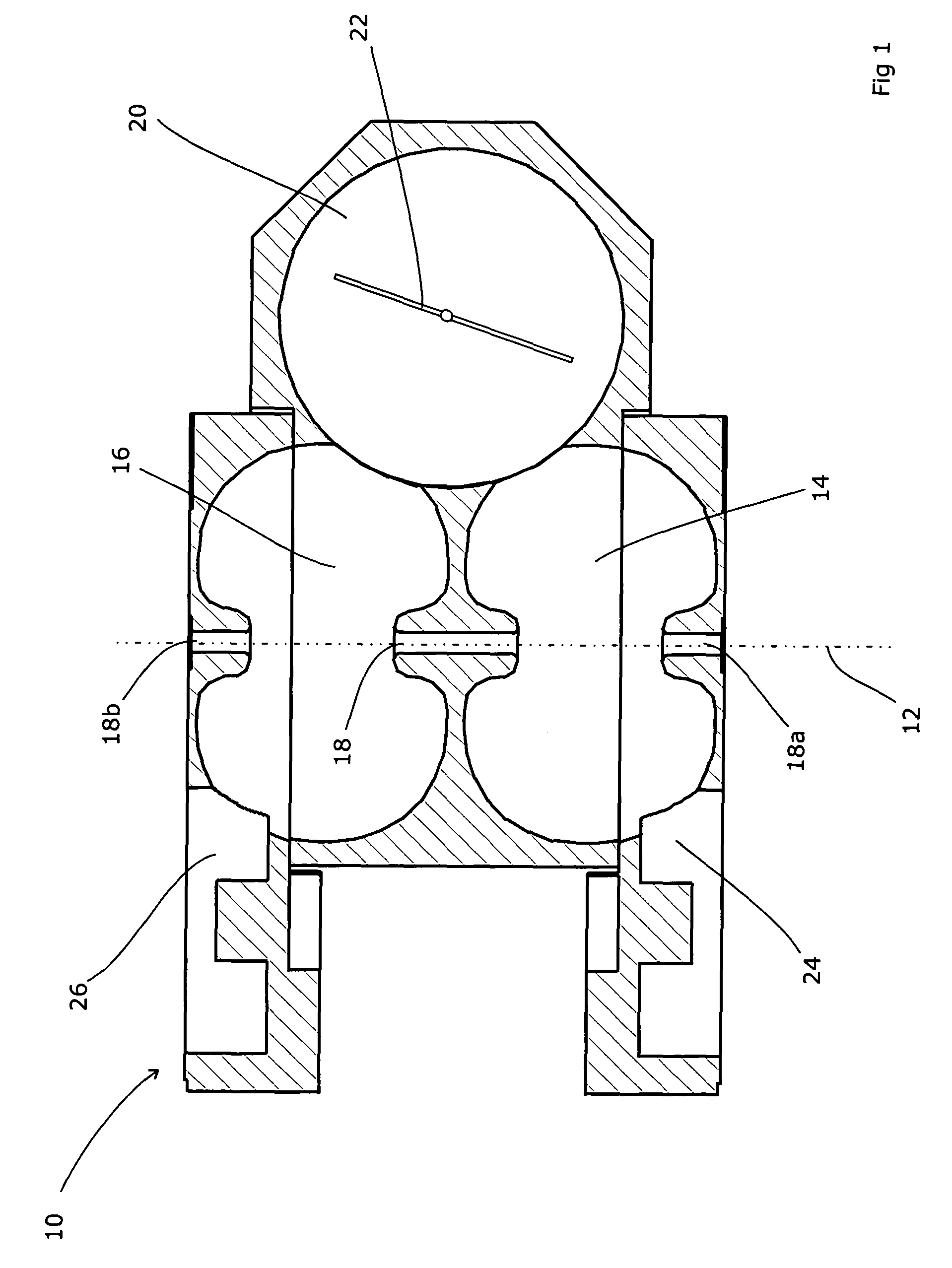
[0023]Our application WO2006 / 097697A1 showed the basis of an x-ray apparatus able to switch effectively ‘instantaneously’ from a therapeutic energy to an imaging energy, to allow imaging during therapy but with no overhead in time and utilising a much simpler construction. FIG. 1 shows the coupling cavity of the linac 10 disclosed in WO-A-99 / 40759 and WO2006 / 097697A1. A beam 12 passes from an ‘nth’ accelerating cavity 14 to an ‘n+1th’ cavity 16 via an axial aperture 18 between the two cavities. Each cavity also has a half-aperture 18a and 18b so that when a plurality of such structures are stacked together, a linear accelerator is produced.

[0024]Each adjacent pair of accelerating cavities can also communicate via “coupling cavities” that allow the radiofrequency signal to be transmitted along the linac and thus create the standing wave that accelerates electrons. The shape and configuration of the coupling cavities affects the strength and phase of the coupling. The coupling cavity ...
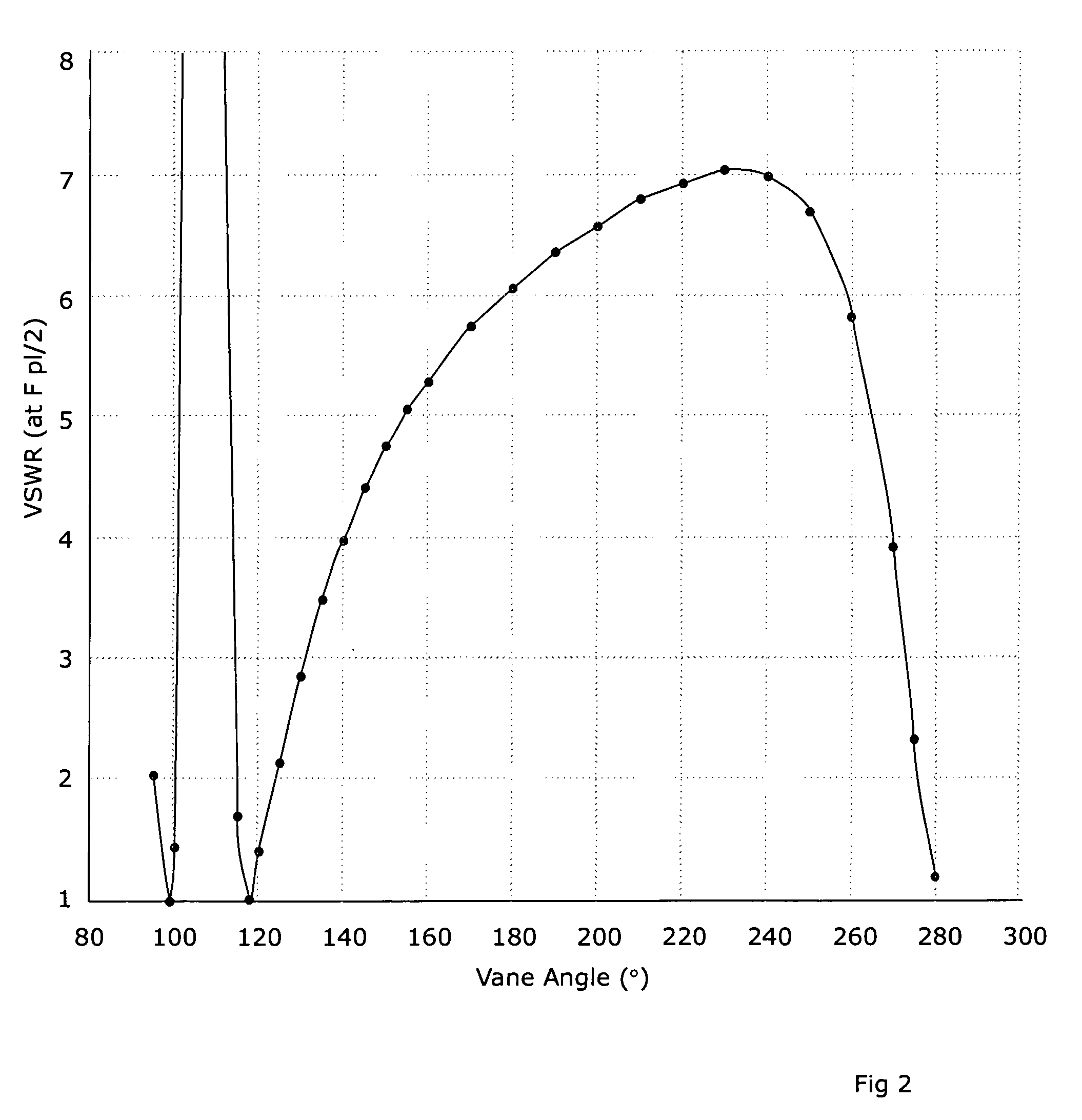

PUM

PropertyMeasurementUnit
vane angle plotaaaaaaaaaa
energyaaaaaaaaaa

Abstract

X-ray apparatus comprises a linear accelerator adapted to produce a beam of electrons at one of at least two selectable energies and being controlled to change the selected energy on a periodic basis, and a target to which the beam is directed thereby to produce a beam of x-radiation, the target being non-homogenous and being driven to move periodically in synchrony with the change of the selected energy. In this way, the target can move so that a different part is exposed to the electron beam when different pulses arrive. This enables the appropriate target material to be employed depending on the selected energy. The easiest form of periodic movement for the target is likely to be a rotational movement. The target can be immersed in a coolant fluid such as water. The linear accelerator can be of the type disclosed in WO2006 / 097697A1. The target preferably contains at least one exposed area of tungsten and / or at least one exposed area of carbon. These can be present as inhomogeneities in the material of which the target is composed, such as Carbon inserts in a Tungsten substrate (or vice versa), alternating segments of Carbon and Tungsten, Carbon and Tungsten inserts in a substrate of a third material, or arrangements involving other materials in addition to or instead of Carbon and / or Tungsten. Alternatively, the target can be of a homogenous material but have inhomogeneities in its thickness to cater for the different electron energies. The same concept can be applied to the filter. A detector can be provided, operating in synchrony with the energy variation. Such an x-ray apparatus can form a part of a radiotherapy apparatus, in which case the first selected energy can be a diagnostic energy and a second selected energy a therapeutic energy.

Description

FIELD OF THE INVENTION[0001]The present invention relates to x-ray apparatus.BACKGROUND ART[0002]In the use of radiotherapy to treat cancer and other ailments, a powerful beam of the appropriate radiation is directed at the area of the patient that is affected. This beam is apt to kill living cells in its path, hence its use against cancerous cells, and therefore it is highly desirable to ensure that the beam is correctly aimed. Failure to do so may result in the unnecessary destruction of healthy cells of the patient.[0003]Several methods are used to check this, and devices such as the Elekta™ Synergy™ device employ two sources of radiation, a high energy accelerator capable of creating a therapeutic beam and a lower energy X-ray tube for producing a diagnostic beam. Both are mounted on the same rotateable gantry, separated by 90°. Each has an associated flat-panel detector, for portal images and diagnostic images respectively.[0004]In our earlier application WO-A-99 / 40759, we desc...

Claims


Application Information

Patent Timeline
Patent Type & Authority Applications(United States)
IPC IPC(8): G01N23/04H05G1/52A61N5/10
CPCH01J35/00H01J2235/08H05H9/04H05H7/12H05H6/00
Inventor BROWN, KEVIN JOHNTHOMPSPM, MARIA GIULIAHANSEN, VIBEKE NORDMARKEVANS, PHILIP MARKROBERTS, DAVID ANTHONY
Owner ELEKTA AB
Why Eureka
Try Eureka