Splice holder for communication socket

a technology for splicing sockets and sockets, applied in the field of splicing socket holders, can solve the problems of not being able to fit with the current wall-based box, not being able to fit together with the normal in-wall standard base box, and not having adequate protection for splicing, so as to facilitate the operation of the communication sockets

Inactive Publication Date: 2010-12-09
CORNING RES & DEV CORP
View PDF23 Cites 17 Cited by
  • Summary
  • Abstract
  • Description
  • Claims
  • Application Information

AI Technical Summary

Benefits of technology

[0007]A first embodiment of present invention provides a splice holder, said splice holder accommodates optical fiber splicing point in a communication socket, so that

Problems solved by technology

However, existing communication sockets which are capable of accommodating both electrical and optical fiber connections are usually large, thus, can only be installed individually or mounted on a special wall-based box and can not be fitted together with a normal in-wall standard base box.
While wall-mounted communication sockets are known that accommodate a plurality of fiber and electrical cable connectors at the same time, they are too larg

Method used


Image

  • Splice holder for communication socket
  • Splice holder for communication socket
  • Splice holder for communication socket

Examples


Embodiment Construction

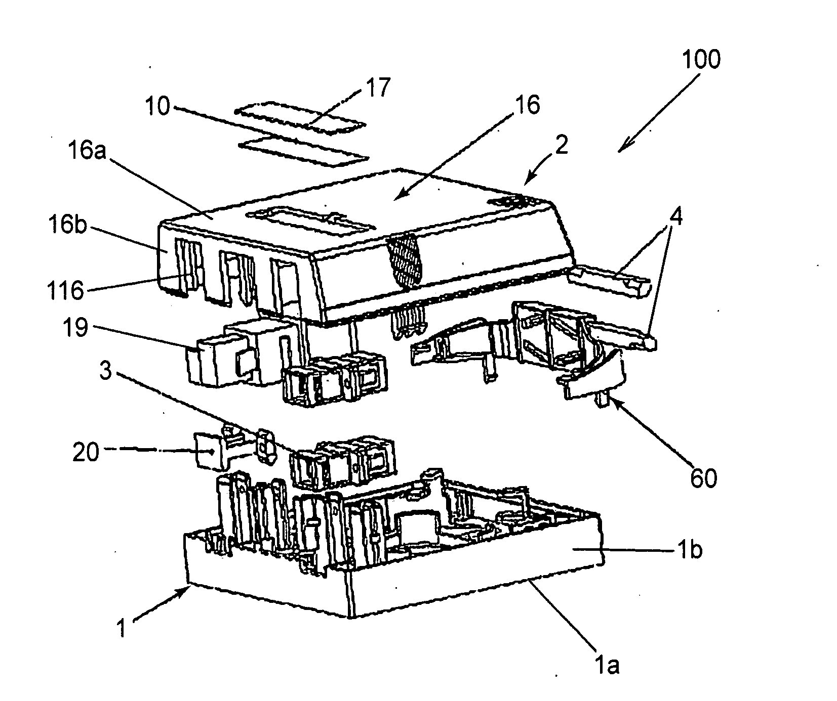
[0023]A splice holder and a communication socket with the splice holder according to the invention will be described in detail in conjunction with the FIGS. 1 to 8.

[0024]FIG. 1 is an exploded perspective view of a communication socket 100 according to an embodiment of the invention. A communication socket 100 as shown in FIG. 1 has a base 1 and a cover 2. The base 1 and the cover 2 can be fitted with each other by a detachable connection configuration, for example, by means of a snap connection. In an embodiment of the invention, the shapes of the base 1 and the cover 2 are rectangular, but those skilled in the art could understand that other shapes may be used instead, and the example is only for illustration purpose rather than limitation

[0025]The cover 2 has a top wall 2a and four side walls 2b. The sidewalls 2b may be attached to the bottom edges of the top wall and extend laterally away from the top wall. In some embodiments, the side walls 2b may be substantially perpendicular...


PUM


Abstract

The present invention discloses a splice holder, which is used for holding at least one splicing sleeve (4), each of the splicing sleeves (4) is used for coupling two optical fibers. The splice holder comprises: a body; a splice channel (7) provided on the body; and an elastic device (9) in each splice channel, wherein the elastic device holds the splicing sleeve (4) elastically in the splice channel. The present invention also includes a communication socket having a splice holder mounted therein. By the splice holder of present invention, optical fiber connection points can be accommodated in a communication socket, so that electrical cables and optical fibers in the communication socket may be managed in an orderly way. Furthermore, inclusion of the inventive splice holder ensures than a minimum bending radius of optical fiber can be maintained when the optical fiber is stored in the communication socket.

Description

FIELD OF INVENTION[0001]The present invention relates to a splice holder, and more particularly, to a splice holder which holds at least one splicing sleeve adapted to couple two optical fibers, and the present invention also provides a communication socket for installing the splice holder, the communication socket is used for connecting the optical fiber and electrical cable in the communication network.BACKGROUND OF INVENTION[0002]In Fiber to the Home (FTTH) and Fiber to the Desk (FTTD) applications, a communication socket may serve as a terminal relay device for optical fibers and electrical cables (e.g. electrical cables, optical cables or coax cables). In the market, conventional communication sockets are installed on a wall surface in a premise or home. The communication sockets permit connection of pre-terminated optical fiber patch cords and electrical cables to the network optical fibers and electrical cables installed either in the walls or on the walls of a home or premis...

Claims


Application Information

Patent Timeline
IPC IPC(8): G02B6/00
CPCG02B6/4441G02B6/4466G02B6/4454G02B6/475
Inventor ZHOU, JUNSHENGBONVALLAT, PIERREXU, ZHIYONG
Owner CORNING RES & DEV CORP
Why Eureka
Try Eureka