Flexible packaging device of a microbattery

a micro-battery and flexible technology, applied in the direction of cell components, sustainable manufacturing/processing, final product manufacturing, etc., can solve the problems of inflexible, inconvenient techniques, and thick cover compared, so as to prevent the occurrence of microcracks, reduce protection, and be flexible and easy to fabricate

Inactive Publication Date: 2010-12-09
COMMISSARIAT A LENERGIE ATOMIQUE ET AUX ENERGIES ALTERNATIVES
View PDF5 Cites 22 Cited by
  • Summary
  • Abstract
  • Description
  • Claims
  • Application Information

AI Technical Summary

Benefits of technology

The invention is a device that packages microbatteries, which solves problems with previous packaging methods. It is flexible and easy to make, while also preventing microcracks that can reduce protection when there is a lot of bending stress.

Problems solved by technology

The technical problem addressed in this patent is the need for a protective barrier for microbatteries that are sensitive to air and other substances, while also being flexible and able to withstand mechanical stresses. The current packaging solutions, such as using glass covers or thin layers of polymer materials, have limitations in preventing diffusion of species that react with lithium. The invention proposes a new packaging device that overcomes these limitations and provides better protection and flexibility for microbatteries.

Method used


Image

  • Flexible packaging device of a microbattery
  • Flexible packaging device of a microbattery
  • Flexible packaging device of a microbattery

Examples


Embodiment Construction

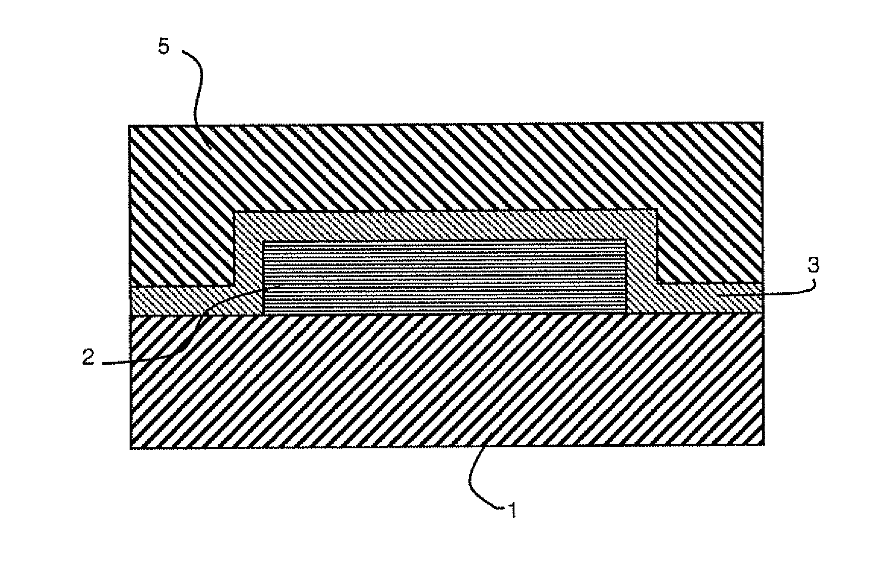
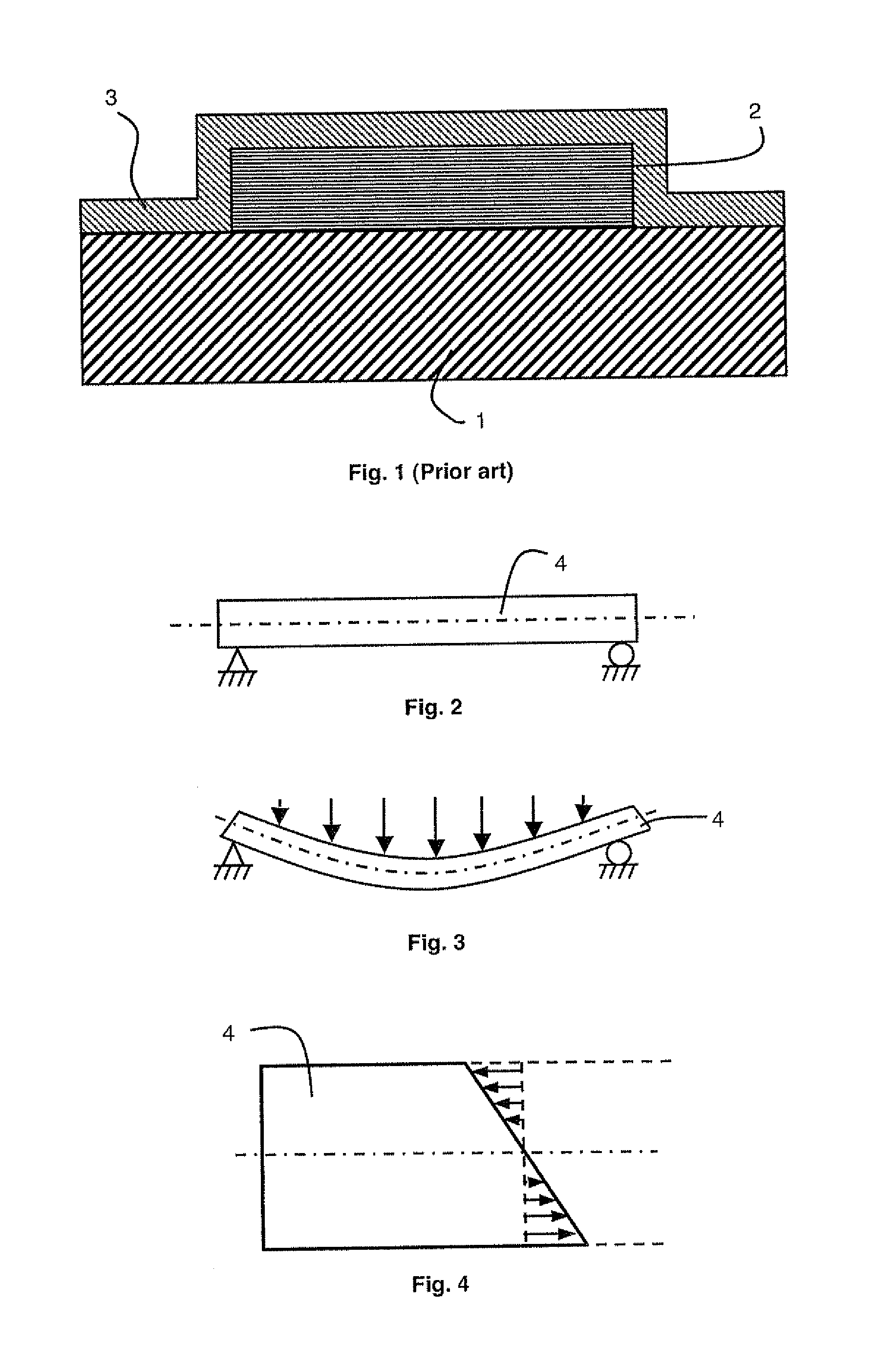
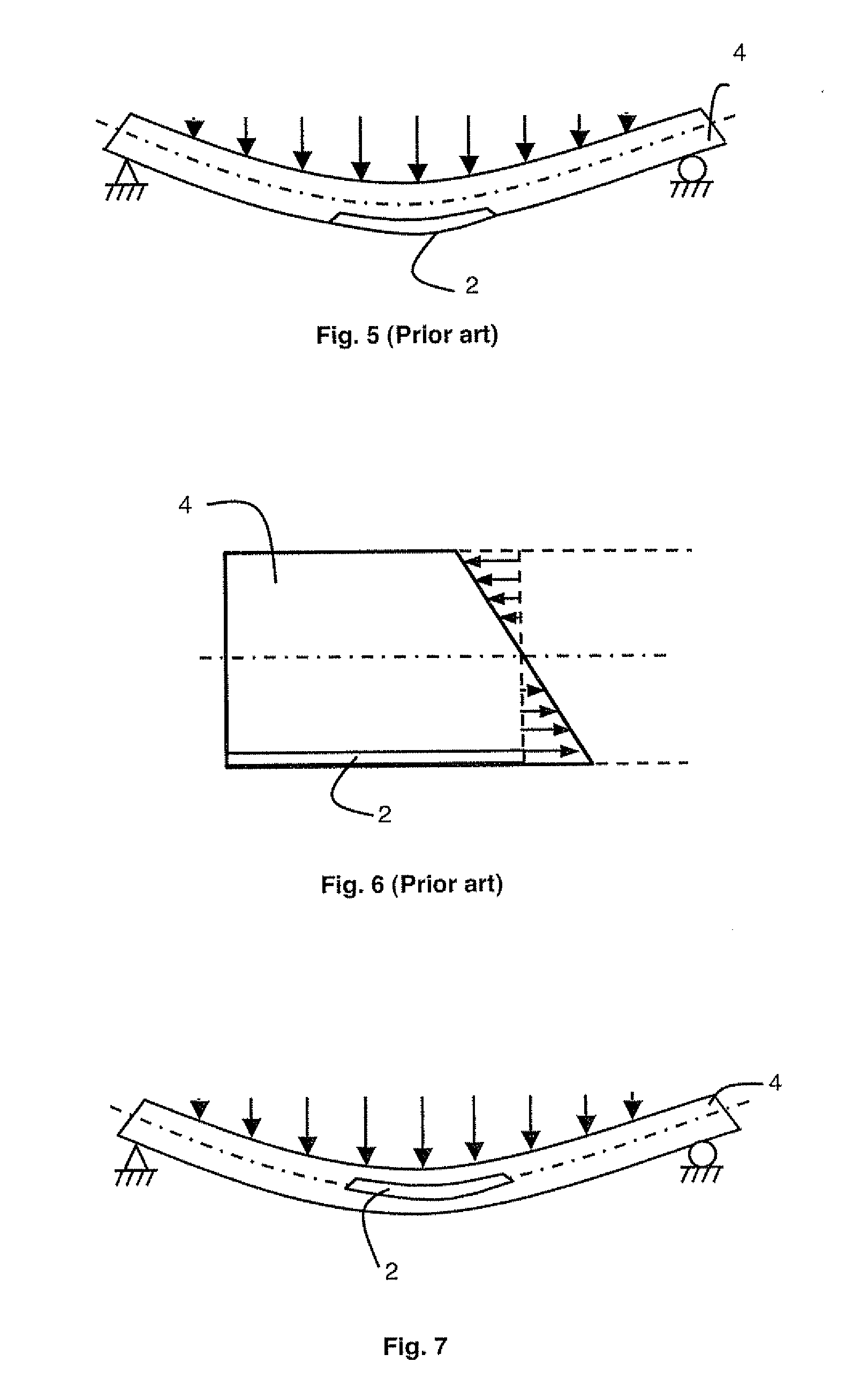
[0026]In the preferred embodiment of FIG. 7, battery 2, covered by its protective barrier (not shown) is placed as close as possible to the neutral plane (represented by the dotted and dashed line) of structure 4. In this area, called neutral plane or neutral axis, the mechanical stresses when flexion occurs are minimal (FIG. 8) and the barrier preserves its integrity. Such a configuration is represented in FIG. 9. The packaging device of microbattery 2, arranged on a surface of flexible support 1, comprises at least one thin layer forming protective barrier 3 and a flexible compensation cover 5. Barrier 3 covered by cover 5 is arranged on microbattery 2 and on support 1 at the periphery of the microbattery.

[0027]Compensation cover 5 is made from a material having a thickness and a Young's modulus that are chosen to have equivalent mechanical properties to that of support 1. The thickness and Young's modulus of the cover are chosen such as to situate the microbattery, arranged on th...


PUM

PropertyMeasurementUnit
Fractionaaaaaaaaaa
Fractionaaaaaaaaaa
Thicknessaaaaaaaaaa

Abstract

The packaging device of a microbattery arranged on a flexible support comprises at least one thin layer forming a protective barrier deposited on the whole of the microbattery, and a flexible compensation cover above the barrier. The cover is made from a material, for example polymer, with a thickness tcomp and a Young's modulus Ecomp chosen such that the neutral plane of the assembly is situated at the level of the microbattery. The thickness of the cover is calculated, with an accuracy of ±30%, by the equation
tcomp=tsubη
in which tsub is the thickness of the support and η the ratio of the Young's moduli of the cover and of the support.

Description


Claims


Application Information

Patent Timeline
Owner COMMISSARIAT A LENERGIE ATOMIQUE ET AUX ENERGIES ALTERNATIVES
Why Eureka
Try Eureka