
Advanced detection of memory device removal, and methods, devices and connectors

a technology of memory devices and detection methods, applied in the direction of memory adressing/allocation/relocation, instruments, computing, etc., can solve the problems of data corruption caused by removing memory cards during erase or programming operations, and data stored in the memory card to be corrupted

Active Publication Date: 2010-12-09
MICRON TECH INC
View PDF1 Cites 34 Cited by
  • Summary
  • Abstract
  • Description
  • Claims
  • Application Information

AI Technical Summary

Benefits of technology

The patent text describes a memory card connector and memory cards that can be easily removed from a host device. However, the removal of the memory card during programming or erase operations may cause data corruption. To address this problem, the patent proposes a device or method that reduces the likelihood of data corruption when removing memory cards during such operations. The technical effect of this invention is to provide a safer way to remove memory cards from a host device without risking data corruption.

Problems solved by technology

Unfortunately, the removal of power from the memory card during programming or erase may cause data stored in the memory card to be corrupted.
However, it may be possible for a user to remove the memory card without providing an remove indication to the host, thereby possibly corrupting data stored in the memory card.
With the recent advent of multi-level flash memory devices, which may store any of 4 or more different charge levels on each floating gate, for example, the problem of data corruption caused by removing memory cards during erase or programming operations may become even more serious.

Method used


Image

  • Advanced detection of memory device removal, and methods, devices and connectors
  • Advanced detection of memory device removal, and methods, devices and connectors
  • Advanced detection of memory device removal, and methods, devices and connectors

Examples


Embodiment Construction

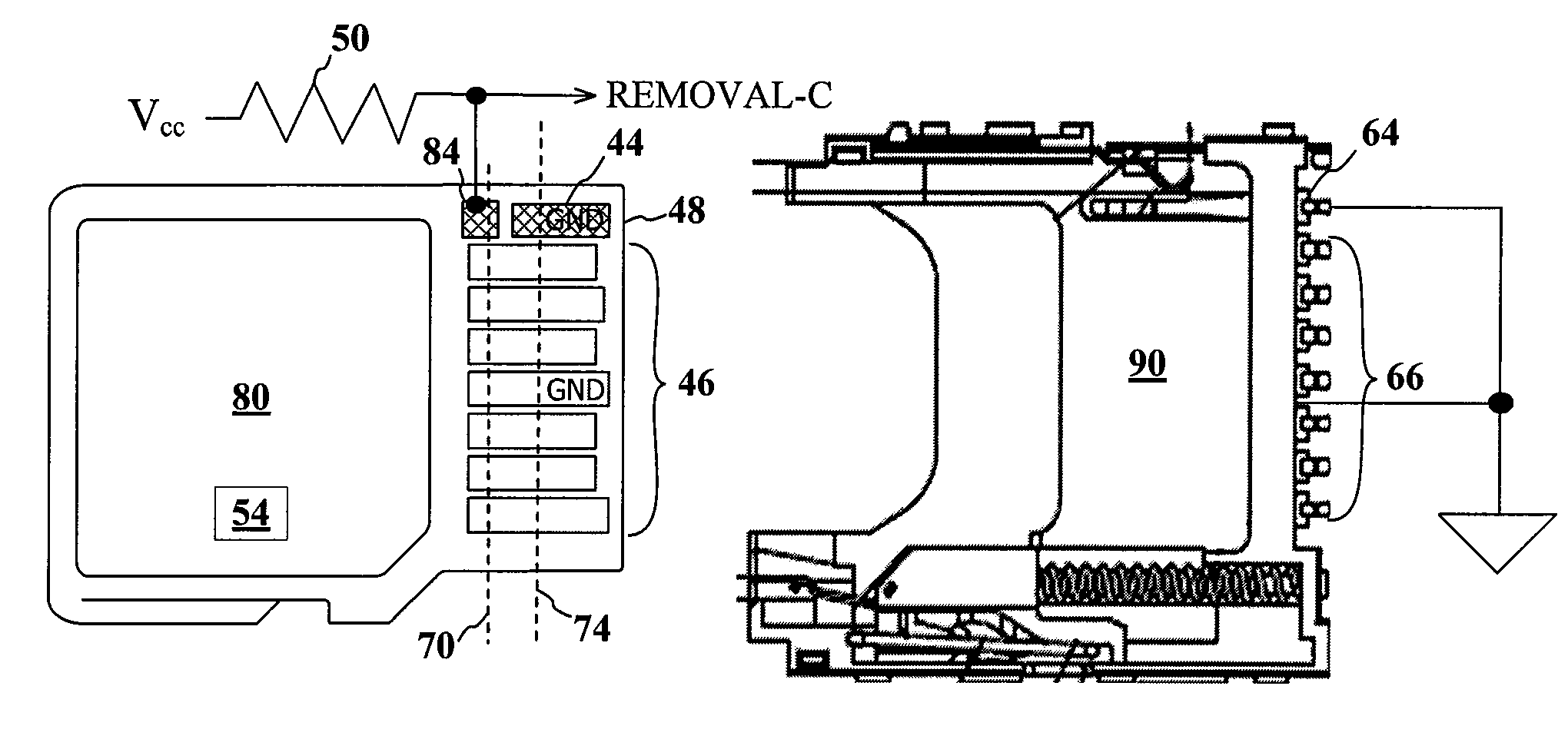
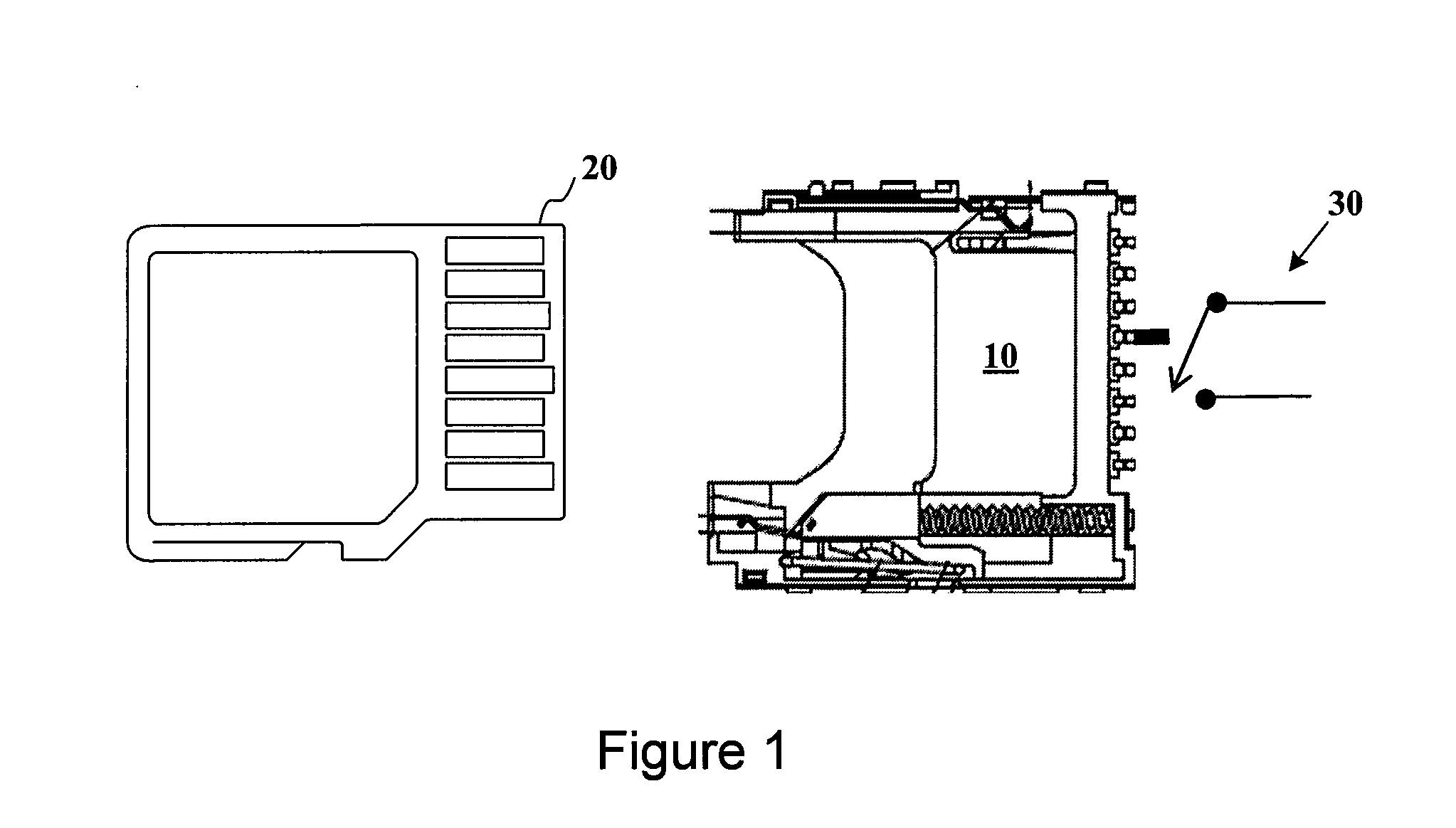
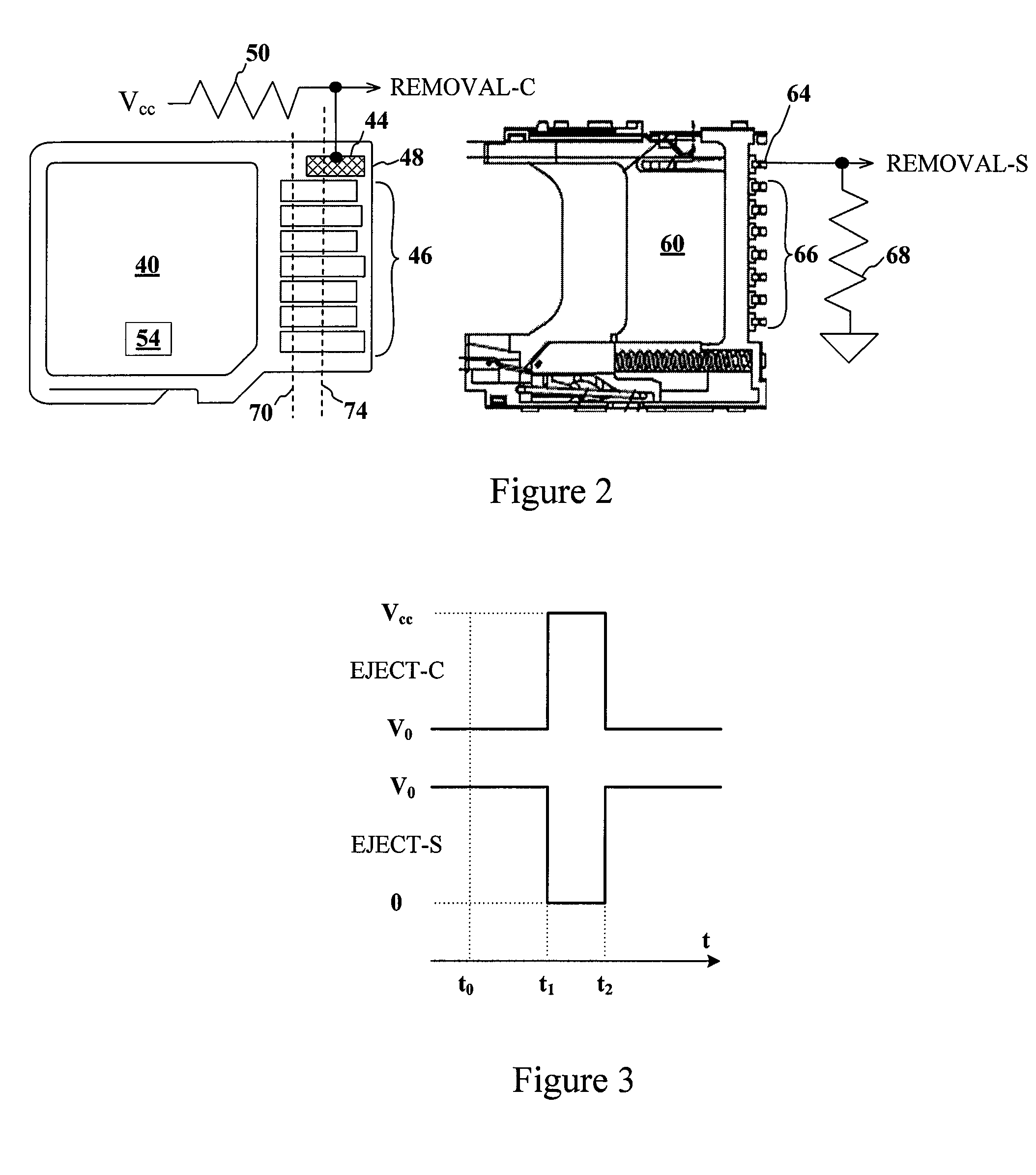
[0016]One embodiment of a memory card connector 10 for receiving a memory card 20 is shown in FIG. 1. In the embodiment shown, the memory card 20 comprises an SD card and the connector 10 comprises an SD card connector, but other memory cards may be used in other embodiments using other types of memory cards and connectors. As is well known in the art, the memory card 20 may be inserted into the connector 10, and ultimately reaches a first position where the memory card may be inserted further against a resilient bias, such as a spring. However, the user may continue to insert the memory card until the card has been completely inserted. When the memory card 20 has been completely inserted, the user may release the memory card 20 to allow the resilient bias to return the memory card 20 to the first position, which latches the memory card 20 in the connector 10.

[0017]The memory card 20 may be at least partially removed from the connector 10 using the reverse sequence of operations. Sp...


PUM


Abstract

Memory devices, connectors and methods for terminating an operation are provided, including a memory device configured to terminate an internal operation such as a programming or erase operation responsive to receiving a signal during removal of the memory device from a connector, such as a socket. The memory device may be specially configured to generate the removal signal, such as by including a dedicated removal terminal. The memory card may respond to the signal by terminating a programming or erase operation before power is lost. The removal terminal may have a dimension that is different from a dimension of a power terminal through which the memory device receives power. Alternatively, the connector may be specially configured to generate a signal that causes a host to terminate programming or erase operations in the memory device prior to memory card removal, such as by including a switch that is actuated when the memory device moves to a pre-power loss position.

Description

TECHNICAL FIELD[0001]Embodiments of this invention relate to memory devices and / or their connectors, and, more particularly, in some embodiments, to memory devices that are normally packaged for insertion and removal in a host, such as a computer or other electronic device using a removable memory device.BACKGROUND OF THE INVENTION[0002]Memory devices, particularly non-volatile memory devices like flash memory, are commonly packaged in a manner that makes it relatively easy for users to insert and remove the memory devices from a host, such as host devices or host systems. Examples of memory devices packaged in this manner include SD Cards, Micro SD Cards, Flash Memory Cards, and CE Cards, to name a few. All of these and other memory devices will sometimes be generically referred to herein as “memory cards,” which is intended to refer to any memory device that may be installed in or removed from a host by means other than soldering or the like. Such memory cards frequently use flash...

Claims


Application Information

Patent Timeline
Patent Type & Authority Applications(United States)
IPC IPC(8): G06F12/00G06F12/02
CPCG06F13/4068
Inventor COOKE, JAMESFEELEY, PETERTSAI, VICTORRADKE, WILLIAM H.GALBO, NEALCOBBLEY, CHAD
Owner MICRON TECH INC
Learn More