Eureka AIR delivers breakthrough ideas for toughest innovation challenges, trusted by R&D personnel around the world.

Computer memory cards using flash EEPROM integrated circuit chips and memory-controller systems

a technology of integrated circuit chips and memory controllers, which is applied in the direction of printed circuit board receptacles, instruments, support structures, etc., can solve the problems of losing the content of the ram, and achieve the effect of convenient us

Inactive Publication Date: 2005-09-20
SANDISK TECH LLC
View PDF94 Cites 123 Cited by
  • Summary
  • Abstract
  • Description
  • Claims
  • Application Information

AI Technical Summary

Benefits of technology

[0012]In specific implementations, two, three or four such memory chips are provided in a row along a rectangularly shaped sub-board having terminals along one of its long dimensions and which is attached to the main board through connection of its terminals with the exposed main board contacts. Several such sub-boards can be installed on the main board, on one or both sides, within the limits of the PC card standard identified above. This sub-board structure permits a large number of EEPROM chips to be included within such a card. It also allows testing of the chips attached to each sub-board before they are assembled together on the main board, thus allowing an early identification of any problems in the mounting and initial interconnection of the circuit chips.
[0015]According to another aspect of the present invention, a flash EEPROM system is provided with physical form factors which match those of industry standard floppy and hard disk drives, along with an electrical interface that emulates such drives. Such a non-volatile flash EEPROM system is then easily usable as an alternative in a computer system designed to include such disk drives.

Problems solved by technology

Semiconductor random access memory (“RAM”) without a battery power supply backup is only temporarily used since it is volatile; that is, when power to the computer system is disconnected, contents of the RAM are lost.

Method used


Image

  • Computer memory cards using flash EEPROM integrated circuit chips and memory-controller systems
  • Computer memory cards using flash EEPROM integrated circuit chips and memory-controller systems
  • Computer memory cards using flash EEPROM integrated circuit chips and memory-controller systems

Examples


Embodiment Construction

[0034]Several physical configurations of a memory card system are described with respect to FIGS. 1-11. An example electronic system within such a card, including both flash EEPROM and controller integrated circuit chips, is described with respect to FIGS. 12-17.

Physical Memory Card Configurations

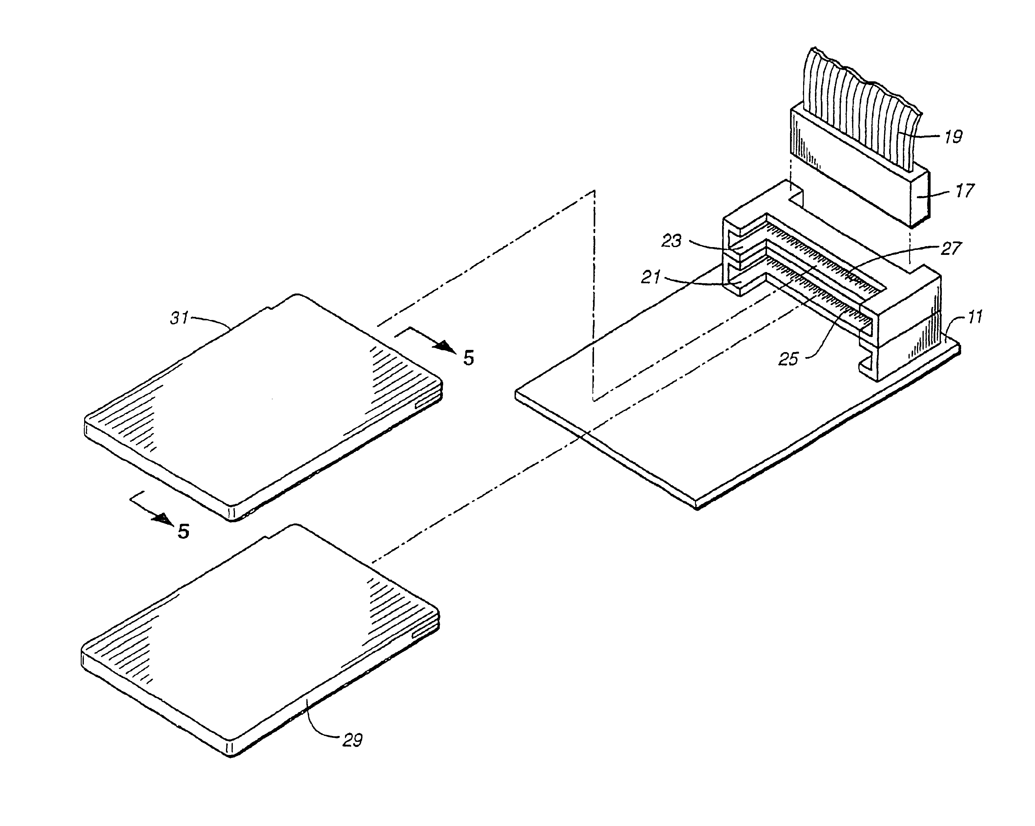
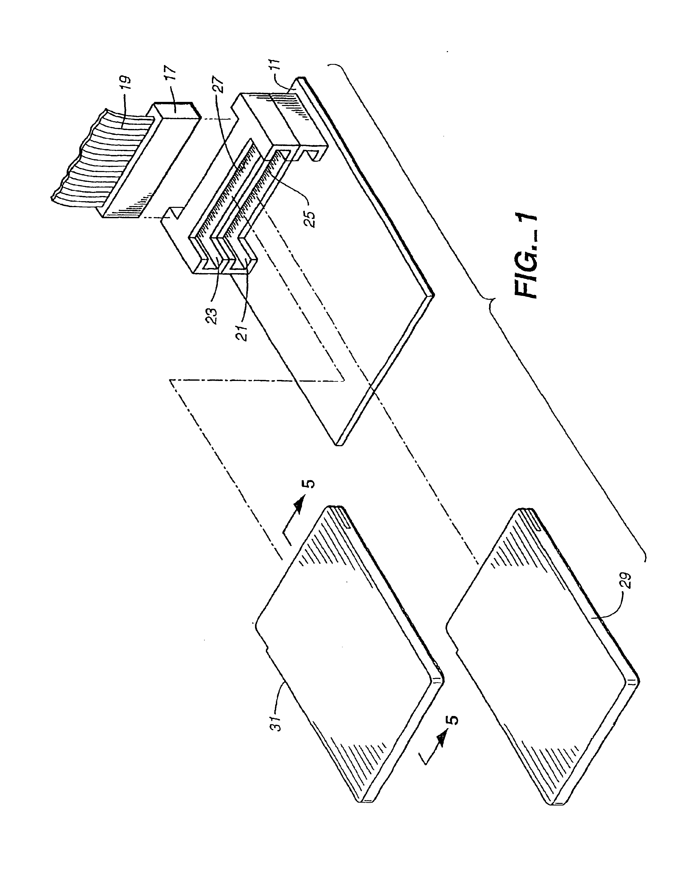
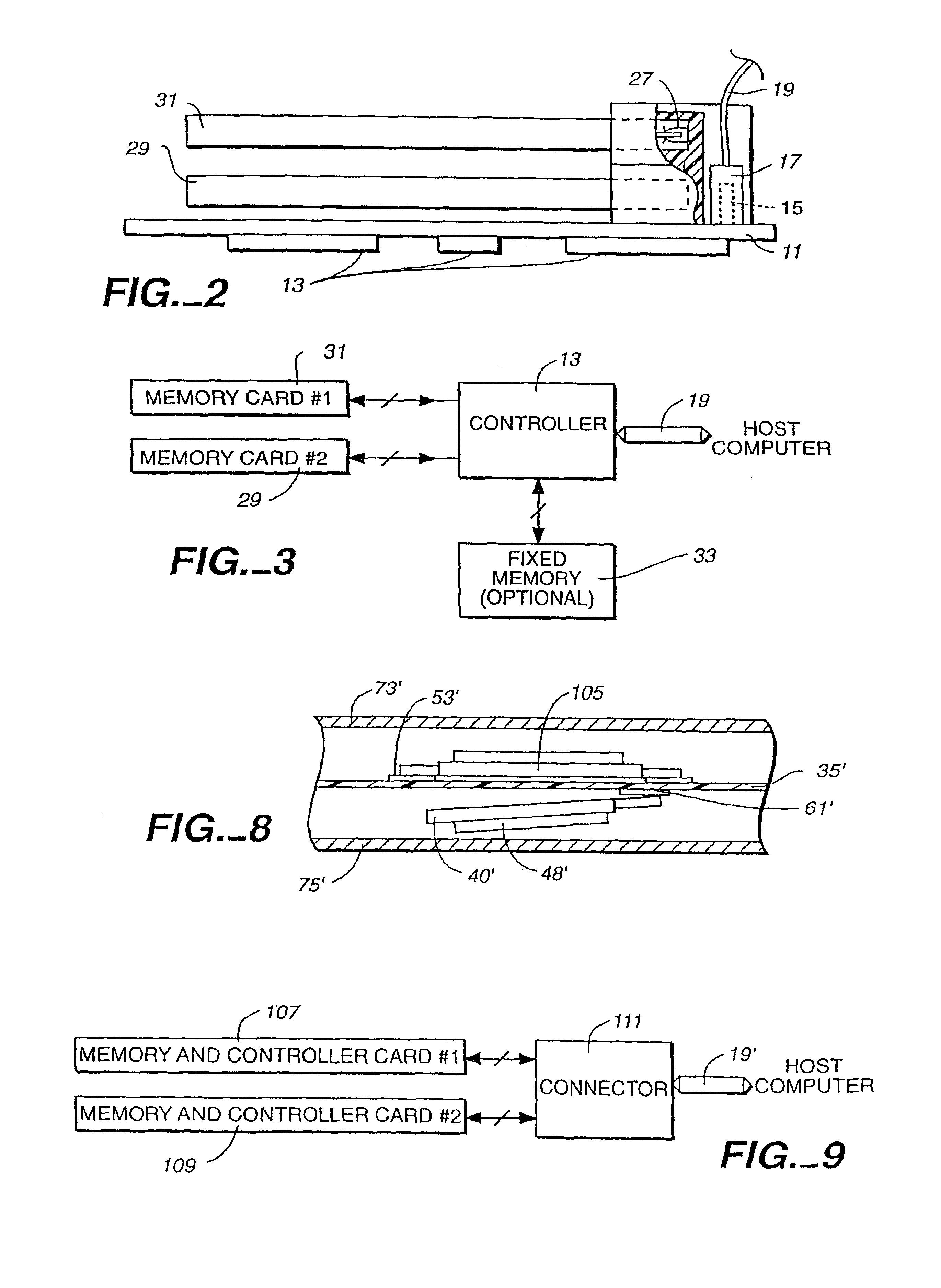
[0035]Referring initially to FIGS. 1-3, one embodiment of a PC card flash EEPROM memory is illustrated. A structurally rigid printed circuit board 11 contains on one side various circuit components 13 that form a memory controller. The controller circuit is operably connected with a row of connector pins 15 attached to the board 11. A connector 17, provided at an end of a ribbon cable 19, is adapted to interconnect the conductors of the cable 19 to the row of pins 15. Another end (not shown) of the ribbon cable 19 is connectable with a microcomputer system bus. Alternatively, the controller board 11 could be provided with a different type of connector that is adapted to fit directly into an...


PUM


Abstract

A very small computer memory card is densely packed with a large number of flash EEPROM integrated circuit chips. A computer memory system provides for the ability to removably connect one or more of such cards with a common controller circuit that interfaces between the memory cards and a standard computer system bus. Alternately, each card can be provided with the necessary controller circuitry and thus is connectable directly to the computer system bus. An electronic system is described for a memory system and its controller within a single memory card. In a preferred physical arrangement, the cards utilize a main circuit board with a plurality of sub-boards attached thereto on both sides, each sub-board carrying several integrated circuit chips.

Description

CROSS-REFERENCE TO RELATED APPLICATIONS[0001]This is a continuation of application Ser. No. 10 / 197,027, filed Jul. 16, 2002 now U.S. Pat. No. 6,628,637, which is a continuation of application Ser. No. 09 / 888,167, filed Jun. 22, 2001, now U.S. Pat. No. 6,434,034, which is a continuation of application Ser. No. 09 / 473,848, filed Dec. 28, 1999, now U.S. Pat. No. 6,252,791, which is a division of application Ser. No. 09 / 121,348, filed Jul. 23, 1998, now U.S. Pat. No. 6,011,741, which is a continuation of application Ser. No. 08 / 907,111, filed Aug. 6, 1997, now U.S. Pat. No. 5,867,417, which is a continuation of application Ser. No. 08 / 527,254, filed Sep. 12, 1995, now U.S. Pat. No. 5,663,901, which is a continuation of application Ser. No. 07 / 736,732, filed Jul. 26, 1991, now abandoned, which is a continuation-in-part of application Ser. No. 07 / 684,034, filed Apr. 11, 1999 now abandoned, all of which are hereby incorporated herein by this reference.[0002]This is also related to another ...

Claims


Application Information

Patent Timeline
Patent Type & Authority Patents(United States)
IPC IPC(8): G11C7/00G11C16/04G06F3/06G06F12/00G06F13/00G06F13/38G06K7/00G11C5/00G11C5/02G11C16/06H05K1/14
CPCG06F3/0601G06F13/385G06K7/0047G06K19/07732G06K19/07741G06K19/07743G11C5/04H05K1/141H05K7/1431G06F2003/0694H05K3/3421H05K2201/10159H05K2201/10462H05K2201/10484H05K2203/1572H01L2224/73265H01L2224/32225H01L2224/48227H01L2924/00H01L2224/48091H01L2224/83385H01L2924/00014G06F3/0664
Inventor WALLACE, ROBERT F.NORMAN, ROBERT D.HARARI, ELIYAHOU
Owner SANDISK TECH LLC
Why Eureka
Eureka Blog
Learn More