
Variable heat exchanger

a heat exchanger and variable technology, applied in the field of semiconductor device systems, can solve the problems of reducing the performance, affecting the operation of the circuit,

Inactive Publication Date: 2010-12-16
THE BOARD OF TRUSTEES OF THE LELAND STANFORD JUNIOR UNIV +1
View PDF46 Cites 36 Cited by
  • Summary
  • Abstract
  • Description
  • Claims
  • Application Information

AI Technical Summary

Problems solved by technology

Many types of modern integrated circuits, implemented in semiconductor chips for example, dissipate significant amounts of power in the form of heat.
If not managed properly, the generated heat may quickly build up and reduce the performance or even cause the failure of such circuits.
The task of removing heat build up from a modern semiconductor chip is complicated by several factors.
The second factor complicating heat management is the tendency for hot spots to move around.
A more complicated conventional heat transfer system for some devices includes a micro-channel heat exchanger that is placed in thermal contact with the device.
Such flow disturbances can cause oscillations or even excursive flow instabilities.
Mechanical strength is one issue associated with the fully porous vapor membrane.
Thermal cycling of micro-channel heat exchangers can cause significant mechanical stresses.
Thermal conductivity is another issue, since the porous material is not as thermally conductive as, say, a material with a higher density.

Method used


Image

  • Variable heat exchanger
  • Variable heat exchanger
  • Variable heat exchanger

Examples


Embodiment Construction

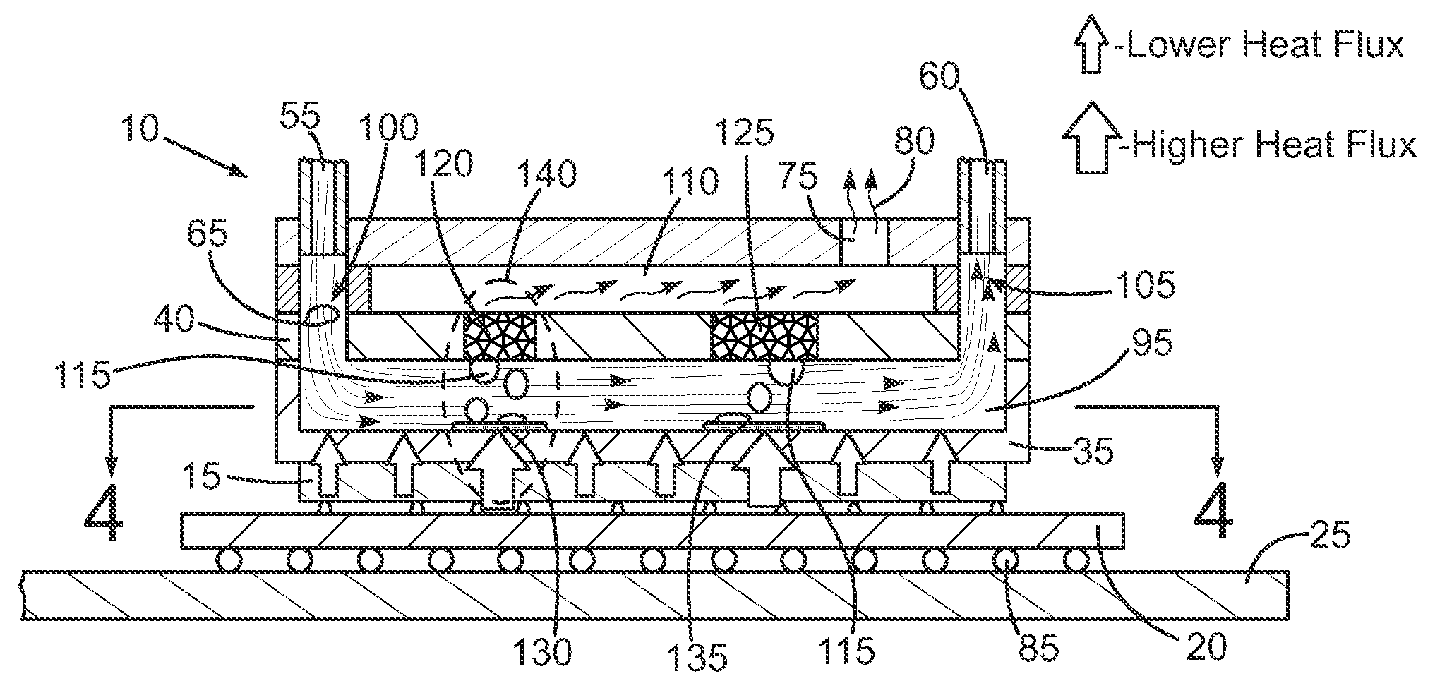
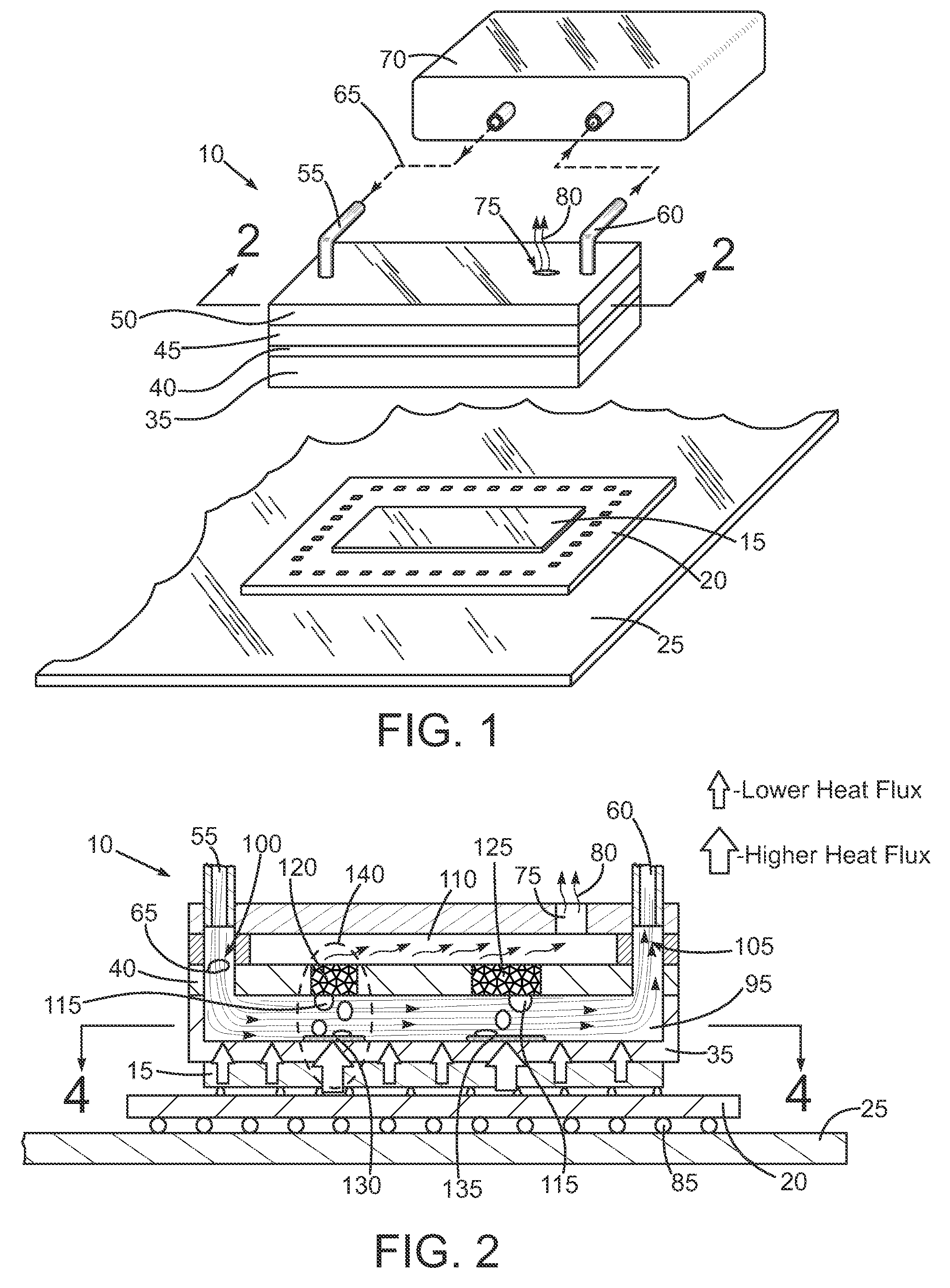
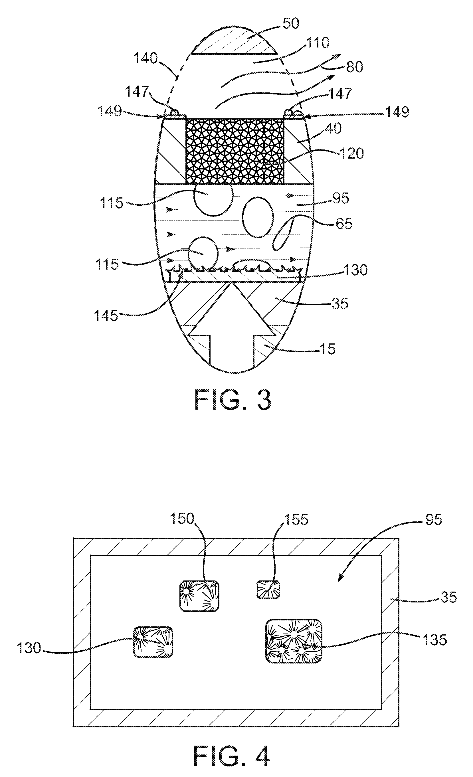
[0011]In accordance with one aspect of an embodiment of the present invention, a method of thermally managing a heat generating device is provided that includes placing a heat exchanger in thermal communication with the heat generating device. The heat exchanger has an interior space. A membrane is in the interior space between a first chamber and a second chamber. The membrane has a gas impermeable portion and at least one gas permeable portion to enable vapor bubbles in the second chamber to pass through the membrane at the at least one gas permeable portion and into the first chamber. A liquid is moved through the second chamber.

[0012]In accordance with another aspect of an embodiment of the present invention, a method of thermally managing a heat generating device is provided that includes placing a heat exchanger in thermal communication with the heat generating device. The heat exchanger has an interior space. A membrane is in the interior space between a first chamber and a s...


PUM


Abstract

Various apparatus and methods for thermally managing a heat generating device. In one aspect, a method of thermally managing a heat generating device is provided that includes placing a heat exchanger in thermal communication with the heat generating device. The heat exchanger has an interior space. A membrane is in the interior space between a first chamber and a second chamber. The membrane has a gas impermeable portion and at least one gas permeable portion to enable vapor bubbles in the second chamber to pass through the membrane at the at least one gas permeable portion and into the first chamber. A liquid is moved through the second chamber.

Description

[0001]This application claims benefit under 35 U.S.C. 119(e) of prior provisional application Ser. No. 61 / 186,674, filed Jun. 12, 2009.BACKGROUND OF THE INVENTION[0002]1. Field of the Invention[0003]This invention relates generally to semiconductor device systems, and more particularly to methods and apparatus for thermally managing semiconductor chips and related devices.[0004]2. Description of the Related Art[0005]Many types of modern integrated circuits, implemented in semiconductor chips for example, dissipate significant amounts of power in the form of heat. If not managed properly, the generated heat may quickly build up and reduce the performance or even cause the failure of such circuits. The task of removing heat build up from a modern semiconductor chip is complicated by several factors. The first factor is the non-uniform structure of current chips. The structure of a typical semiconductor chip varies greatly from edge to edge and from top to bottom. Some areas have highe...

Claims


Application Information

Patent Timeline
IPC IPC(8): G05D23/00F28D15/00
CPCF28D15/0266F28D21/0015F28F27/02G05D23/192H01L23/427H01L2924/0002H01L2924/00
Inventor REFAI-AHMED, GAMALDAVID, MILNESMARCONNET, AMYMILER, JOSEFFLYNN, ROGERGOODSON, KENNETH E.
Owner THE BOARD OF TRUSTEES OF THE LELAND STANFORD JUNIOR UNIV
Learn More