Belt drive for feeding welding wire

a belt drive and welding wire technology, applied in welding apparatuses, manufacturing tools, transportation and packaging, etc., can solve the problems of small wire shavings being separated from the moving wire strand, deformation of the wire, and substantial force applied to the wire during feeding

Active Publication Date: 2010-12-16
ILLINOIS TOOL WORKS INC
View PDF1 Cites 30 Cited by
  • Summary
  • Abstract
  • Description
  • Claims
  • Application Information

AI Technical Summary

Problems solved by technology

Unfortunately, since there is typically a small contact area between the drive rolls and the wire, a substantial force is applied to the wire during feeding.
Such a force may lead to deformation of the wire, and can even cause the

Method used


Image

  • Belt drive for feeding welding wire
  • Belt drive for feeding welding wire
  • Belt drive for feeding welding wire

Examples


Embodiment Construction

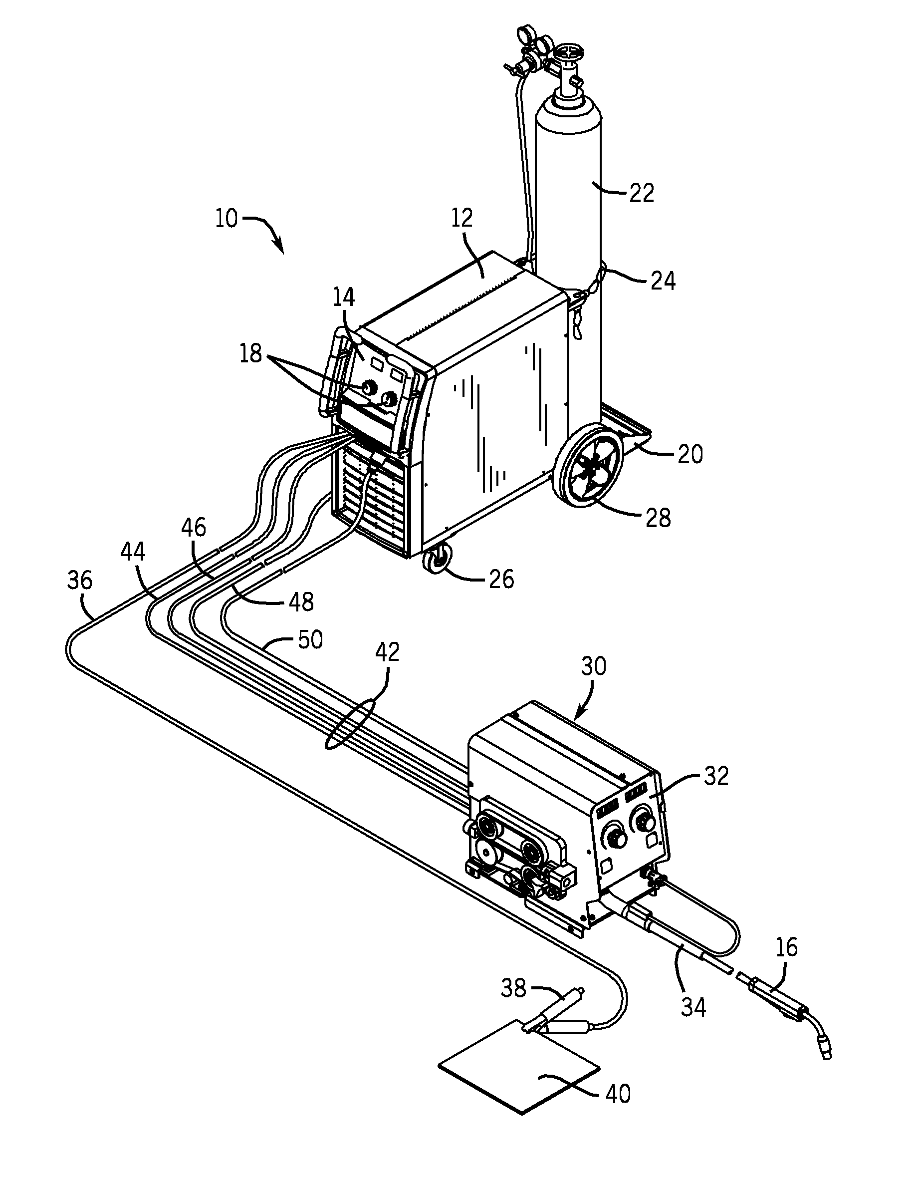
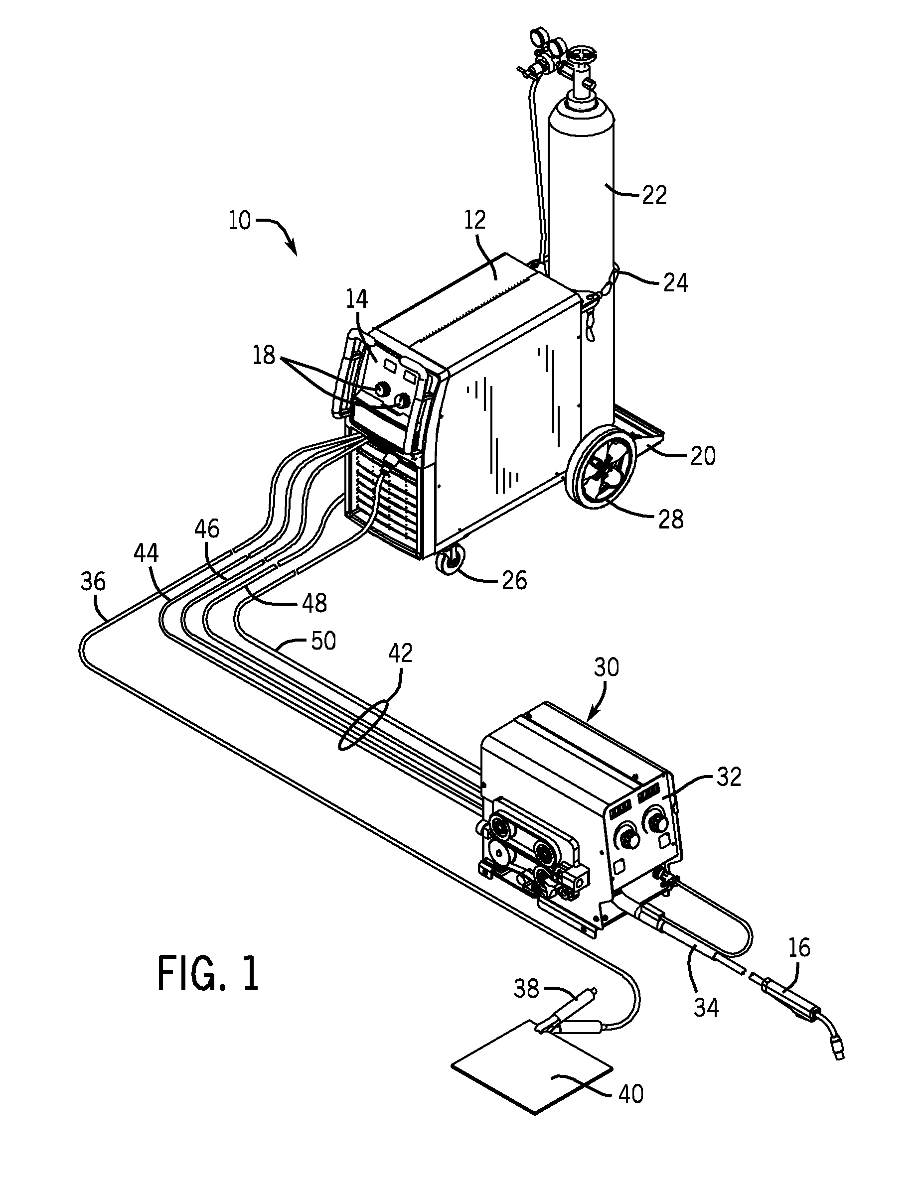
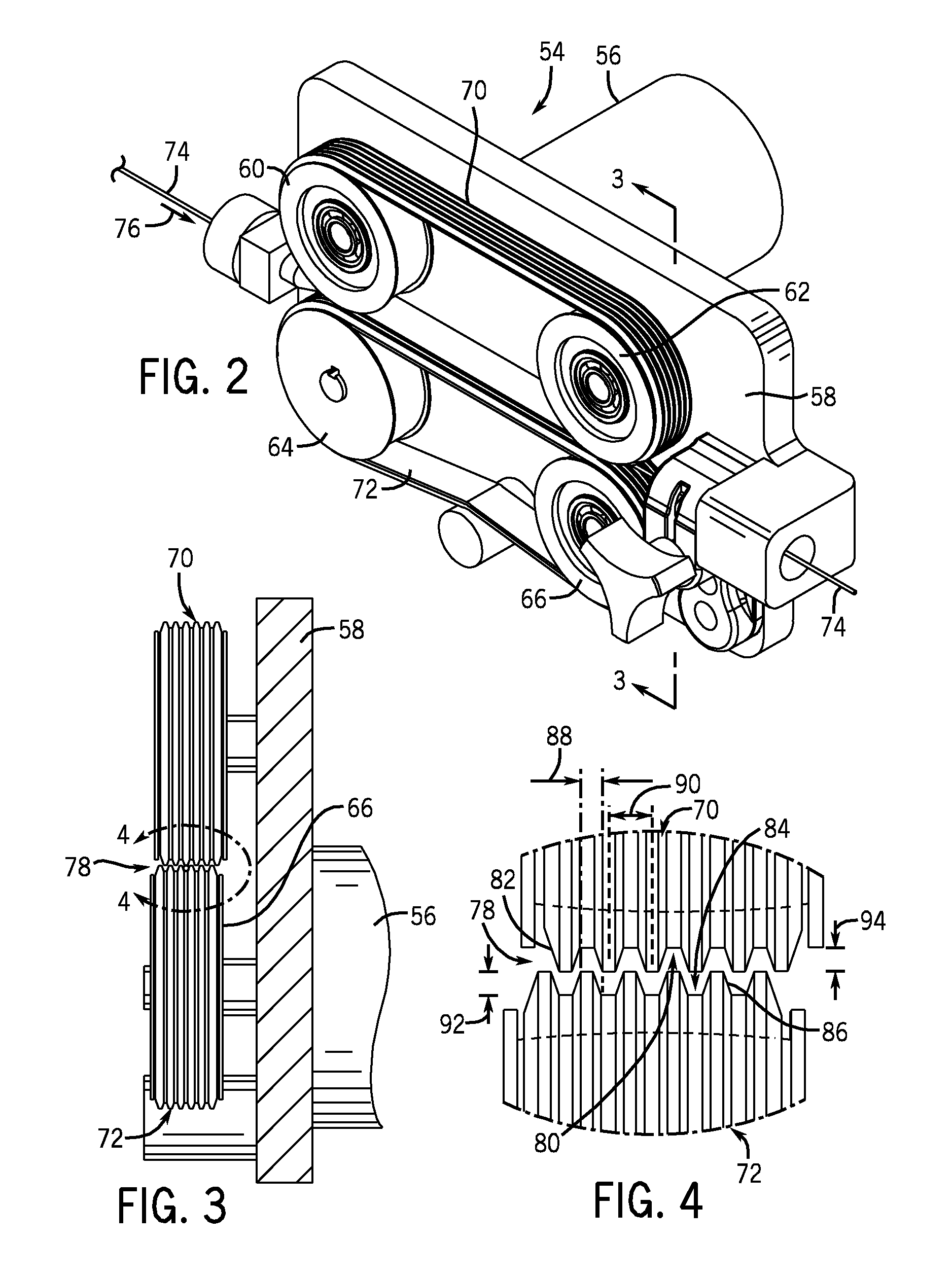
[0021]As described in detail below, embodiments are provided of a welding wire drive system including one or more back-driven belts mounted on wire drive rollers or pulleys, as referred to generally in the following discussion as “rollers”. That is, in embodiments of the present invention, one or more belts may include grooves and projections, which may be generally v-shaped, may be coupled to wire rollers of a welding wire system, one or more of which may serve as a drive roller for driving the belt(s) in continuous circulation to drive welding wire. Where the belt(s) are grooved, the wire may be positioned in opposing grooves or between a groove and a projection, the arrangement forming one of a variety of possible interfacing arrangements suitable for driving the welding wire. As such, the grooves and projections of the belts may be utilized to facilitate both drawing the welding wire from the wire spool and driving the wire through a weld cable to a welding torch. In some embodi...


PUM

PropertyMeasurementUnit
Pressureaaaaaaaaaa
Widthaaaaaaaaaa

Abstract

A welding wire feed drive system is provided including belts mounted on wire drive rollers. One or both belts may be poly-V belts mounted on the rollers and positioned such that grooves of the belts are outward facing. Opposing grooves and projections of the belts may form an interfacing or interlocking arrangement suitable for the securement of a welding wire therein. The grooves and projections of the belts may be utilized to facilitate the movement of the welding wire towards a welding application.

Description

CROSS REFERENCE TO RELATED APPLICATIONS[0001]This application is a Non-Provisional patent application of U.S. Provisional Patent Application No. 61 / 186,186, entitled “Apparatus for Feeding Welding Wire During a Welding Process Using a Poly-V Belt Drive”, filed Jun. 11, 2009, which is herein incorporated by reference.BACKGROUND[0002]The invention relates generally to wire feeding systems, and, more particularly, to wire feed drive systems.[0003]Welding is a process that has become increasingly ubiquitous in various industries and applications. While such processes may be automated in certain contexts, a large number of applications continue to exist for manual welding operations. Such welding operations rely on a variety of control schemes to ensure the supply of welding consumables (e.g., wire feed, shielding gas, etc.) is provided to the weld in an appropriate amount at the desired time. For example, metal inert gas (MIG) welding relies on a proper welding wire feed rate to prevent...

Claims


Application Information

Patent Timeline
IPC IPC(8): B23K9/12
CPCB23K9/1336B65H51/14
Inventor PATTERSON, JON MICHAEL
Owner ILLINOIS TOOL WORKS INC
Why Eureka
Try Eureka