Adapter plate for airplane structure

a technology for adapters and airplanes, applied in aircraft accessories, aircraft floors, aircraft components, etc., can solve the problems of aircraft structure, inability to consider the load path of the fuselage structure in said direction, and the pallet itself cannot be considered as a load path in the direction of the fuselage structure, so as to reduce the thickness of the wall

Inactive Publication Date: 2010-12-16
JET AVIATION
View PDF2 Cites 32 Cited by
  • Summary
  • Abstract
  • Description
  • Claims
  • Application Information

AI Technical Summary

Benefits of technology

[0009]The problem is solved by an adapter plate which acts as a load carrying structure interconnectable to an existing load carrying structure of the airplane fuselage without negative influence of the overall static concept. The adapter plate acts as an adapter between a device, such as one or more seats or another installation and the load carrying structure of the fuselage. The device is attached to the adapter plate only and / or to more than one adapter plate and / or the existing structure and an adapter plate. In general the adapter plate when interconnected to the load carrying structure of the airplane functionally forms part of said load carrying structure and not of the installation. In general an adapter plate according to the herein discussed invention may be attached reversible to the longitudinal and / or transversal floor beams of the fuselage. Thereby reversible modifications are possible without negative impact of the existing structure.
[0010]In certain cases it is foreseen that the fixation of the adapter plate has a certain degree of freedom in a specific direction with the aim that at least one end can be displaced under certain conditions. Thereby the adapter plate does not influence the overall load path in a negative manner but still is capable to transfer the load applied to it. In one embodiment this is achieved by holes having an oblong cross-section (oblong holes). The inside of the oblong holes may be plated to avoid damage of the surface.
[0013]To avoid negative impact of existing load paths the fastening means at least partially are holes with an oblong cross section in general extending in the direction of the central beam area. In a preferred embodiment the central beam area has in longitudinal direction an in general U-shaped cross-section. The arms of the U-shaped cross-section may comprise fastening means to fasten at least one floor panel. By the herein described adapter plate it becomes possible to successfully withstand dynamic testing of e.g. a seat installation at 16 g dynamic peak load test. A further advantage is that no considerable fatigue load is introduced in the seat track beams.

Problems solved by technology

In addition, the pallet itself, due to its short length and dimensions compared to the whole aircraft structure, can not be considered as a load path for the fuselage structure loads in said direction.

Method used


Image

  • Adapter plate for airplane structure
  • Adapter plate for airplane structure
  • Adapter plate for airplane structure

Examples


second embodiment

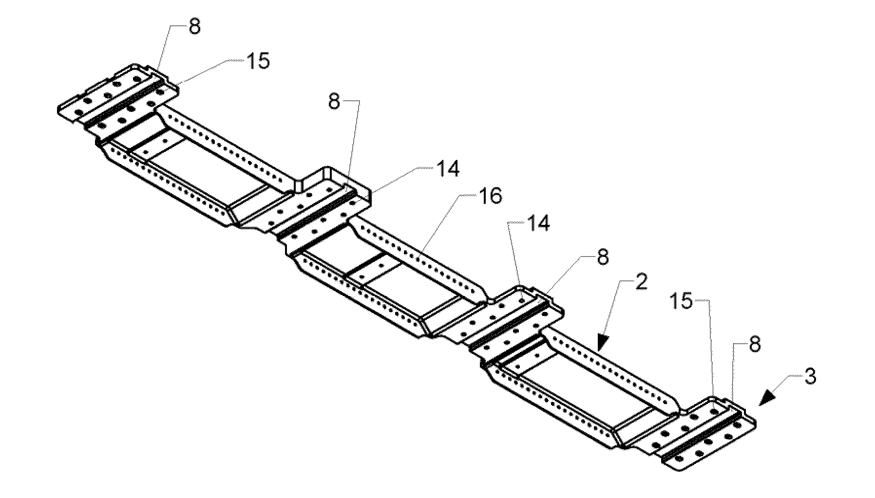
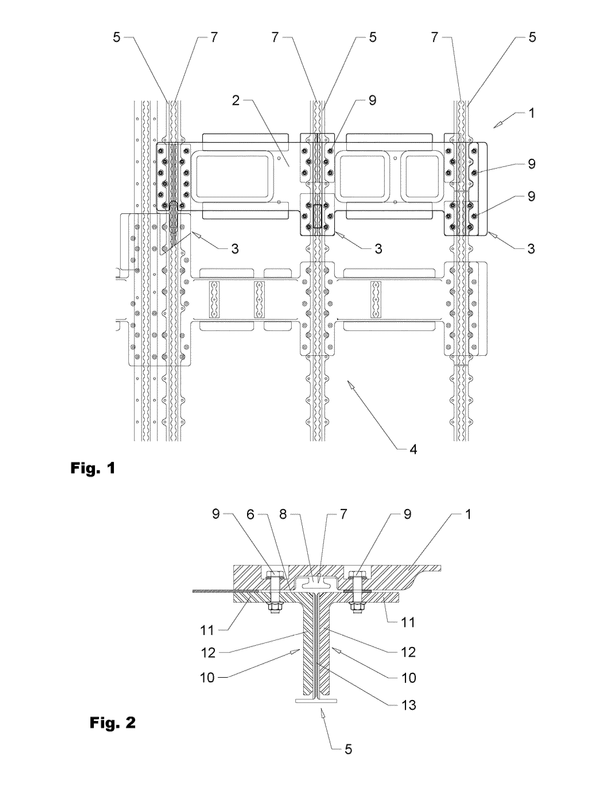
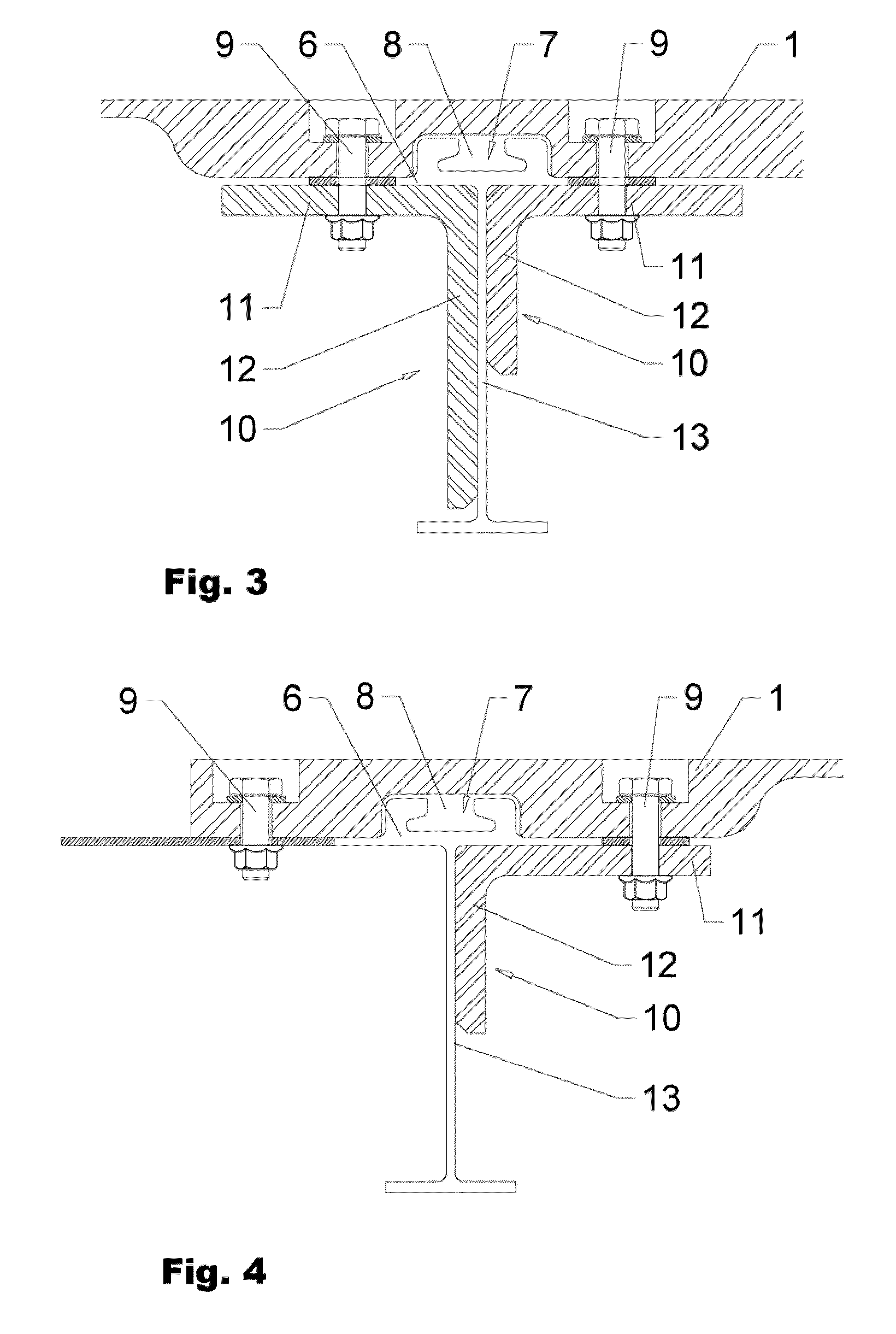
[0041]FIGS. 5 through 9 show an adapter plate 2 in a perspective view from top (FIG. 5) and from bottom (FIG. 6). FIG. 7 is showing the adapter plate in a top view and FIG. 9 in a front view. FIG. 8 is showing detail A of FIG. 7.

[0042]The shown embodiment comprises a central beam section 2 which is designed to in a mounted position extend across four in general parallel floor beams of a fuselage structure of an airplane (not visible). At the position of the floor beams the adapter plate 1 comprises stubs 3 by which the adapter plate 1 can be attached to the floor beams. Depending on the size and the functionality of the individual floor beams the stubs 3 have an individual design. Each stub 3 comprises a channel 8 arranged in a transversal direction with respect to the floor beams suitable to receive and encompass existing seat track rails mounted on top of the floor beams (see FIGS. 2 through 5).

[0043]The adapter plate 1 can extend over 2 or more floor beams. To reduce influence on...

fourth embodiment

[0044]FIGS. 10 through 14 is showing a third and FIGS. 15 through 18 is showing an adapter plate 1 in a perspective view from top (FIGS. 10 and 15) and from bottom (FIGS. 11 and 16). FIGS. 12 and 17 are showing the adapter plates 1 in a top view and FIGS. 14 and 18 in a front view. FIG. 13 is showing detail B of FIG. 12

[0045]The adapter plates 1 according to the FIGS. 10 through 18 in general correspond to the second embodiment according to FIGS. 5 through 9. Therefore, with respect to the general description reference is made to said Figures. Similar features are carrying corresponding reference signs. Although all examples are showing adapter plates 1 with a lateral extension across three floor beams it is possible to realize adapter plates which reach across a different number of floor beams.

[0046]In the embodiment according to FIGS. 15 through 18 stubs 3 are arranged at an angle a with respect to the lateral extension of the central beam part 2. The respective channels 8 are arr...


PUM


Abstract

The invention is directed to an adapter plate (1) for interconnecting of a device with an airplane structure. The adapter plate (1) comprises a central beam (2) area extending in a mounted position across at least two longitudinal and / or lateral floor beams (5) of a fuselage of an airplane and at least two stubs (3) arranged at an angle to the central beam area (2) in the general direction of the floor beams. The adapter plate (1) comprises fastening means to interconnect the adapter plate (2) to the floor beams (5) whereby the stubs comprise at least one channel (8) to receive an existing seat track (7) mounted on a floor beam (5).

Description

FIELD OF THE INVENTION[0001]The invention relates to an adapter plate (pallet) for flexible implementation of load into an existing airframe, i.e. fuselage structure of an airplane.BACKGROUND OF THE INVENTION[0002]Modifications to airplane structures are strictly regulated by Aviation Safety Agencies, such as EASA in Europe and the FAA in the USA and according manuals provided by the manufacturer of the vessels.[0003]In airplanes passenger seats and other internal facilities are normally attached to the fuselage structure of an airplane by standardized rail systems which suit as load application means also for all other installations. The rails of said rail systems are attached to or form part of longitudinal or transversal beams of the fuselage positioned underneath the rails. The beams in general are arranged grid like and form part of the overall load carrying structure of the airplane fuselage. Therefore modification to said structure is very critical. Problems which may occur a...

Claims


Application Information

Patent Timeline
Patent Type & Authority Applications(United States)
IPC IPC(8): B64C1/06
CPCB64C1/20B64D11/0696
Inventor GASSER, MICHELGRETHER, PETERSCHRAMM, JOCHENRIETSCH, THIERRY
Owner JET AVIATION
Why Eureka
Try Eureka