Elimination of errors due to aging in magneto-resistive devices

a technology of magnetoresistive devices and aging, applied in the field of magnetic measurements, to achieve the effect of reducing the impact of measurement accuracy

Active Publication Date: 2010-12-16
HEADWAY TECH INC
View PDF8 Cites 24 Cited by
  • Summary
  • Abstract
  • Description
  • Claims
  • Application Information

AI Technical Summary

Benefits of technology

[0015]It has been an object of at least one embodiment of the present invention to

Problems solved by technology

What limits the 1B and 1C circuits, as implemented in the prior art,

Method used


Image

  • Elimination of errors due to aging in magneto-resistive devices
  • Elimination of errors due to aging in magneto-resistive devices
  • Elimination of errors due to aging in magneto-resistive devices

Examples


example 1a

(1) Example 1a

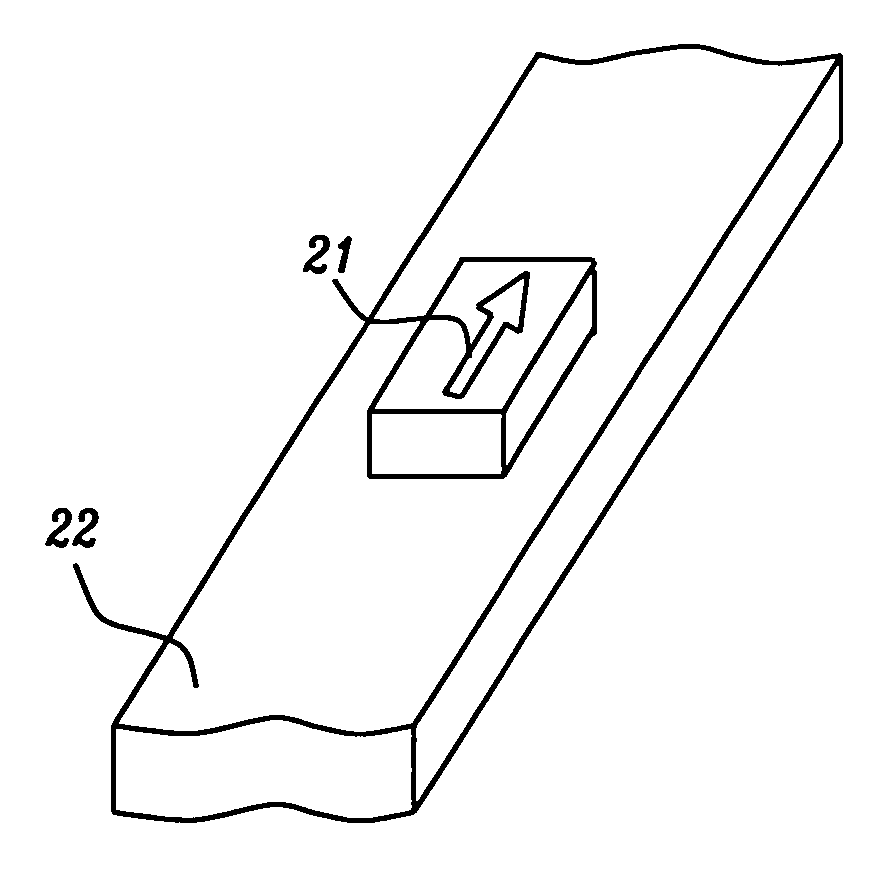
[0046]This example is based on the ‘current source replacing voltage source’ described immediately above where the normalizing factor is the sensor resistance in either the HR or LR state. The value of current source 26 is the current flowing through sensor 21 when voltage source 25 is applied while sensor 21 resistance is either the Hr or the LR resistance.

example 1b

[0047]This example is based on the ‘current source replacing voltage source’ described immediately above except that the normalizing factor is calculated from the sensor resistance in both the HR and LR states. The value of current source 26 is calculated from these LR and HR currents so as to reflect the current flowing through sensor 21 when voltage source 25 is applied; sensor 21 resistance is then a linear function of both the HR and LR resistance such as, for example, but not limited to, the mean sensor resistance when voltage source 25 is present, i.e. the arithmetic average of the HR and LR resistances.

example 2

(2) Example 2

[0048]This example is the same as example 1b, except that magnetic field 23 (generated by 21) is pre-calibrated so that the specifics of particular magnetic environment 23, when produced by passing the same current in 22, are effectively identical. Also, when current in 22 is applied to generate field 23 in sensor 21, the external field is temporarily turned off or shielded out so that the field at 21 is 23 only. By applying voltage source 25, and later replacing it with current source 26 so that the same current flows through sensor 21 when voltage source 25 and field 23 are applied, normalization of sensor 21 resistance is by the resistance of the sensor in a particular magnetic environment 23. In this scheme, field 23 does not need to saturate sensor 21 but rather only needs good repeatability and stability.


PUM


Abstract

The problem of magneto-resistive sensor drift with age has been solved by normalizing the sensor's output relative to its output when it is in a selected reproducible state. Details for the method to accomplish this normalization are disclosed together with several examples of how the method can be utilized.

Description

FIELD OF THE INVENTION[0001]The invention relates to the general field of magnetic measurements with particular reference to measuring magnetic field strength and correcting such measurements for the effects of sensor aging.BACKGROUND OF THE INVENTION[0002]Using magneto resistive (MR) sensors for magnetic field sensing as replacements for the Hall sensors currently being used in commercial products, has the advantage of much higher sensitivity. By using state-of-the-art magnetic tunnel junction (MTJ) sensors, sensitivities an order of magnitude greater than that of Hall sensors can be achieved.[0003]The use of MR devices as current sensors in circuits to which they are not connected (by sensing the magnetic fields associated with these circuits) is disclosed in the Prior Art[1-2]. FIG. 1A shows the general structure of a closed-loop current field sensor. It has three key parts—MR sensor 1, current carrying electric line 3, and field-canceling electric line 4. The current in electric...

Claims


Application Information

Patent Timeline
IPC IPC(8): G11B20/18
CPCG01R33/098G11B5/3906G11B27/36G11B2005/0016G11B2220/2516
Inventor ZHOU, YUCHENGORMAN, GRACE
Owner HEADWAY TECH INC
Why Eureka
Try Eureka