Methods and Apparatus for Reducing Average-to-Minimum Power Ratio in Communications Signals

a technology of communication signals and power ratios, applied in the field of communication systems and methods, can solve the problems of significant energy efficiency reduction, low energy efficiency, and high energy efficiency when pa, and achieve the effect of reducing the average-to-minimum power ratio (ampr)

Active Publication Date: 2010-12-16
APPLE INC
View PDF4 Cites 9 Cited by
  • Summary
  • Abstract
  • Description
  • Claims
  • Application Information

AI Technical Summary

Benefits of technology

[0023]Methods and apparatus for reducing the average-to-minimum power ratio (AMPR) in communications signals are disclosed. An exemplary AMPR-reducing apparatus includes a baseband circuit that includes a baseband modulator, a pulse-shaping filter, and an AMPR reduction circuit. The baseband modulator is configured to generate a sequence of symbols formatted in accordance with a non-constant envelope modulation scheme. The pulse-shaping filter band-limits the sequence of samples to provide a sequence of samples. The AMPR reduction circuit then analyzes and modifies one or more samples in the sequence of samples, if a sample in the sequence of samples that has been previously analyzed by the AMPR reduction circuit is determined to have a magnitude less than a predetermined low-magnitude threshold.

Problems solved by technology

However, for reasons discussed below, a significant drawback of the quadrature-modulator-based transmitter 200 is that it is not very energy efficient, particularly when the modulation scheme being employed is a non-constant envelope modulation scheme.
While employing power back-off does help to ensure PA linearity, it results in a significant reduction in energy efficiency.
Energy efficiency is therefore high when the PA is operating at high RF output powers, but low when the PA is operating at low RF output powers.
This is the primary reason power back-off results in a substantial reduction in energy efficiency.
Low energy efficiency is undesirable in most any application.
It is particularly undesirable in battery-powered RF transmitters, such as those used in cellular handsets, since it results in reduced battery life.
The high signal bandwidths are manifested as high-frequency events in the amplitude and angle component signals ρ and θ and are highly undesirable.
Not only do the high-frequency events tend to degrade the modulation accuracy of the polar transmitter 400, they also cause the transmission spectrum to extend beyond its intended band-limited channel, resulting in adjacent channel interferers and an increase in receive band noise (RxN).
These effects can be very difficult to deal with, especially when modulation accuracy and noise limitation standards must be adhered to.
However, it can be deficient or even detrimental in others, particularly in applications that employ modulation schemes having signal constellation points near or concentrated near the origin in the complex signal plane.
When the conventional hole blowing technique is applied to such signals, the signal trajectory is altered more than is necessary and, as a consequence, the modulation accuracy of the transmitter is significantly degraded.
For other types of signals, the conventional hole blowing technique is ineffective at reducing the AMPR of the signals to levels necessary to reduce out-of-band transmission energy to required or desired levels.
Another problem with the conventional hole blowing technique is that there is no way to be sure or to verify that the signal trajectory of the modified baseband signal ŝ(t) has been pushed outside the low-magnitude threshold, as intended, once the hole blowing process has been applied.
In fact, once the hole blowing process has been applied there is no way of even being sure that the modified signal trajectory avoids passing through the origin.

Method used


Image

  • Methods and Apparatus for Reducing Average-to-Minimum Power Ratio in Communications Signals
  • Methods and Apparatus for Reducing Average-to-Minimum Power Ratio in Communications Signals
  • Methods and Apparatus for Reducing Average-to-Minimum Power Ratio in Communications Signals

Examples


Embodiment Construction

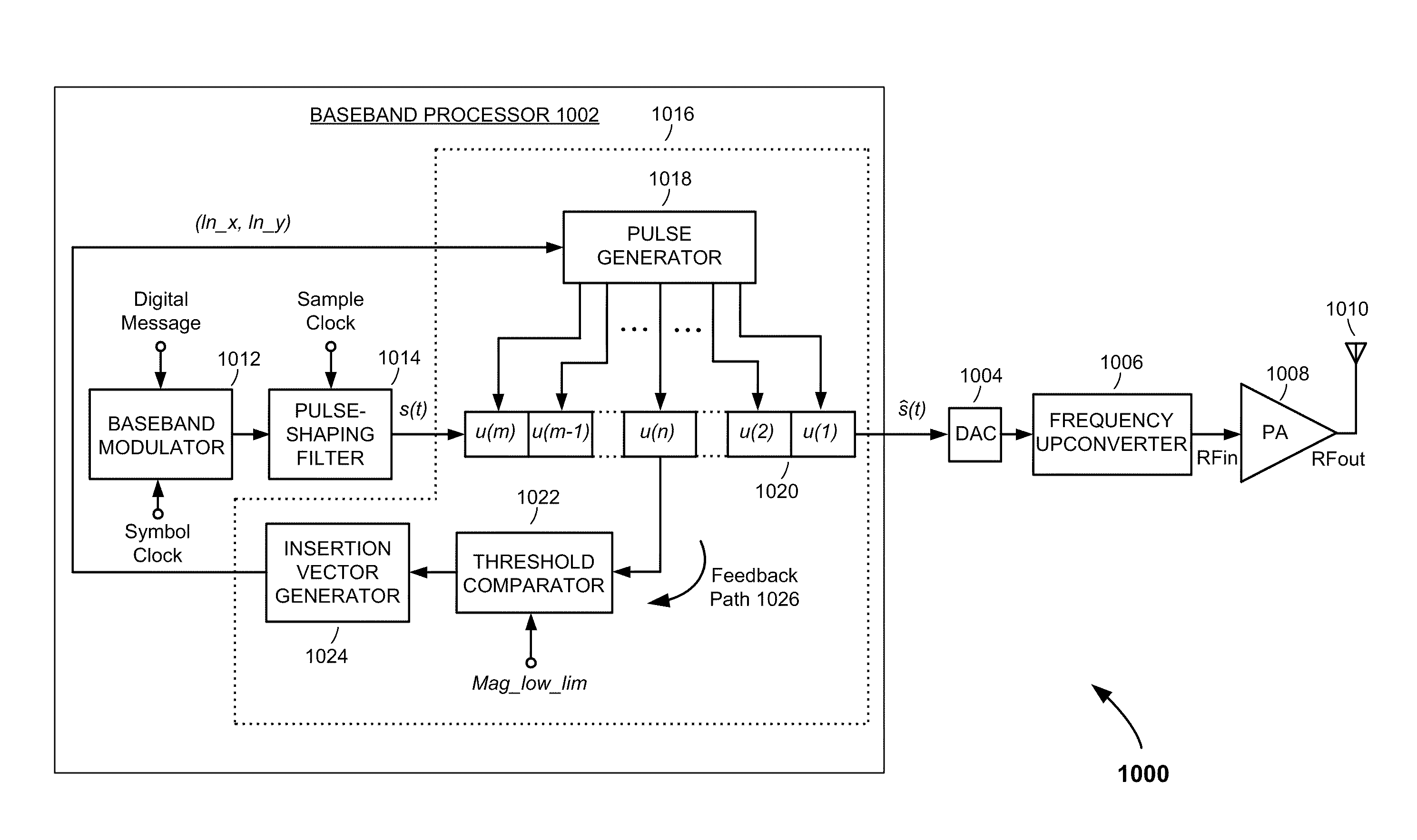
[0047]Referring to FIG. 10, there is shown a radio frequency (RF) transmitter 1000, according to an embodiment of the present invention. The RF transmitter 1000 comprises a baseband processor 1002, a digital-to-analog converter (DAC) 1004, a frequency upconverter 1006, a power amplifier (PA) 1008, and an antenna 1010. The baseband processor 1002 comprises a baseband modulator 1012, a pulse-shaping filter 1014, and an average-to-minimum power ratio (AMPR) reduction circuit 1016. The baseband processor 1002, DAC 1004, frequency upconverter 1006 and PA 1008 are formed in one or more integrated circuits. In the exemplary embodiment described here, the baseband processor 1002, including the baseband modulator 1012, pulse-shaping filter 1014, and AMPR reduction circuit 1016, are formed as a digital signal processor (DSP) in a single integrated circuit. The DSP may implemented as hardware or a combination of hardware and software, such as a microprocessor, microcontroller, field-programmab...


PUM


Abstract

A baseband circuit for a communications transmitter includes a baseband modulator, a pulse-shaping filter, and an AMPR reduction circuit. The baseband modulator is configured to generate a sequence of symbols formatted in accordance with a non-constant envelope modulation scheme. The pulse-shaping filter is configured to band-limit the sequence of samples to provide a sequence of samples. The AMPR reduction circuit is configured to analyze and modify one or more samples in the sequence of samples, if a sample in the sequence of samples that has been previously analyzed by the AMPR reduction circuit is determined to have a magnitude less than a predetermined low-magnitude threshold.

Description

FIELD OF THE INVENTION[0001]The present invention relates to communications systems and methods. More specifically, the present invention relates to methods and apparatus for reducing the average-to-minimum power ratio (AMPR) in communications signals.BACKGROUND OF THE INVENTION[0002]Radio frequency (RF) communications is used in a wide variety of modern-day communications applications, including military, satellite, public health and safety, television, cellular, and wireless area network communications applications. A key component of any RF communications system is the RF transmitter. As illustrated in FIG. 1, an RF transmitter 100 generally comprises a baseband processor 102, a frequency upconverter 104, a power amplifier (PA) 106 and an antenna 108. The purpose of the baseband processor 102 is to generate a baseband signal s(t) that contains a message to be transmitted and which is formatted in accordance with a predetermined modulation scheme. The purpose of the frequency upco...

Claims


Application Information

Patent Timeline
Patent Type & Authority Applications(United States)
IPC IPC(8): H04L27/36H04L27/00
CPCH03F1/3241H03F3/24H04L27/361H04L27/363
Inventor LIANG, PAUL CHENG-POWANG, HUAMORI, KENICHI
Owner APPLE INC
Why Eureka
Try Eureka