
Portable phone holder and solar charger

a solar charger and portable technology, applied in the field of portable electronic devices, can solve the problems of affecting the use of cellular phones, and affecting the use of cellular phones, and achieve the effect of charging more quickly

Inactive Publication Date: 2010-12-16
TAN QING SONG
View PDF10 Cites 52 Cited by
  • Summary
  • Abstract
  • Description
  • Claims
  • Application Information

AI Technical Summary

Benefits of technology

[0006]Circuitry in the cellular phone holder and solar charger of the invention is adapted so that if a cellular phone engaged thereto is in need of charging, power from a battery in the cellular phone holder and solar charger or external power supplied thereto (e.g., from an electrical outlet or from the solar cells) will charge the cellular phone's battery. The cellular phone holder and solar charger itself is connectable to an external power supply so that the battery therein can be charged more quickly and / or the solar cells can provide all the electrical energy to recharge the battery in the unit.

Problems solved by technology

A consistent problem with cellular phones and PDAs, particularly those that are rich in features, such as internet browsers, video capabilities, texting, music playback and other features is that they use a considerable amount of electrical power, and their batteries tend to run down quickly.
While battery chargers are used to recharge cellular phones at electrical outlet plugs and from accessory power plugs in vehicles, many times a cellular phone user does not have access to these sources to recharge their cellular phone batteries.
However, many of these chargers are bulky and impede usage of the cellular phone while the cellular phone is connected to the charger, and there accordingly remains a need for an improved cellular phone holder and charger.
Thus, one of the biggest problems facing cellular phone users out in the field where electrical power is often not available to recharge a phone or emergency situations where power is not available anywhere, is addressed.

Method used


Image

  • Portable phone holder and solar charger
  • Portable phone holder and solar charger
  • Portable phone holder and solar charger

Examples


Embodiment Construction

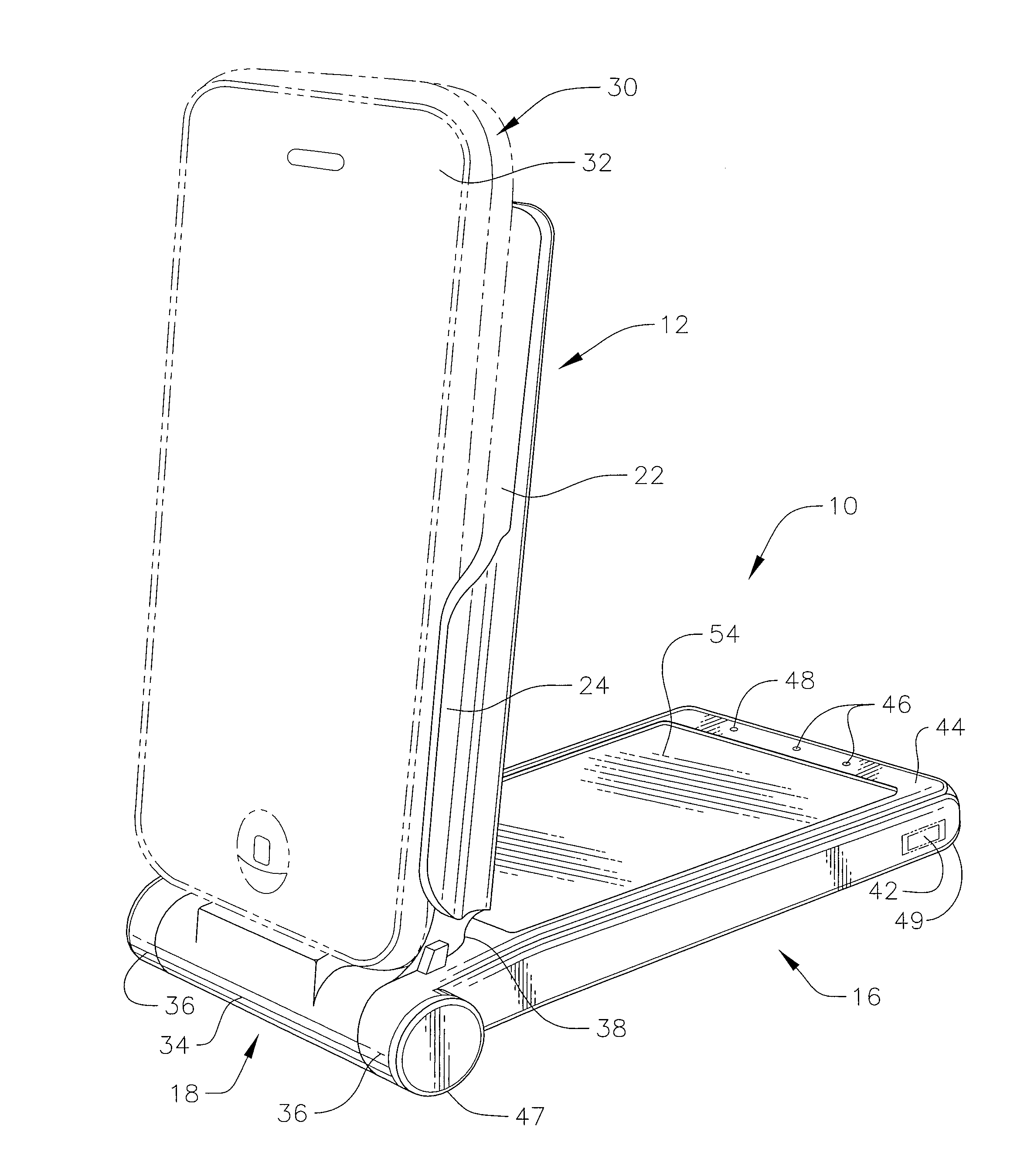
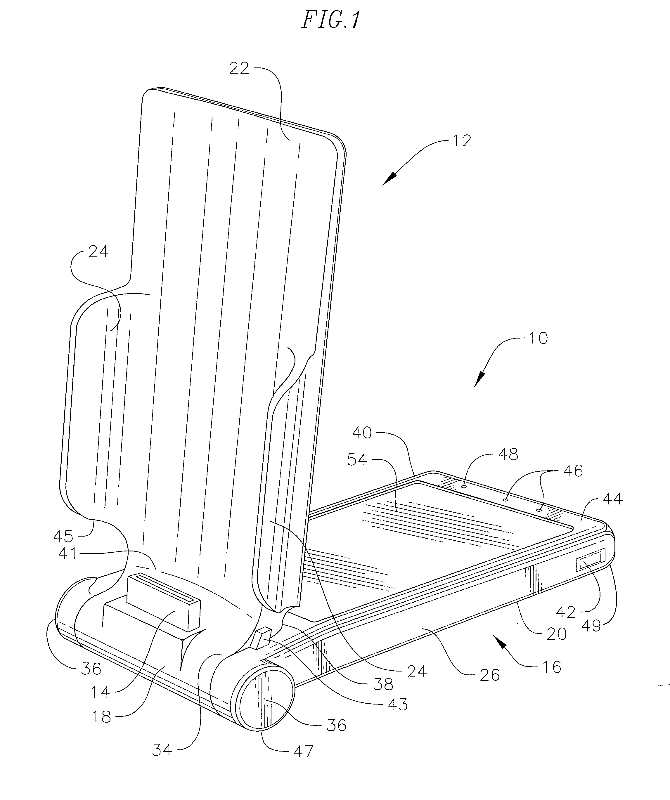
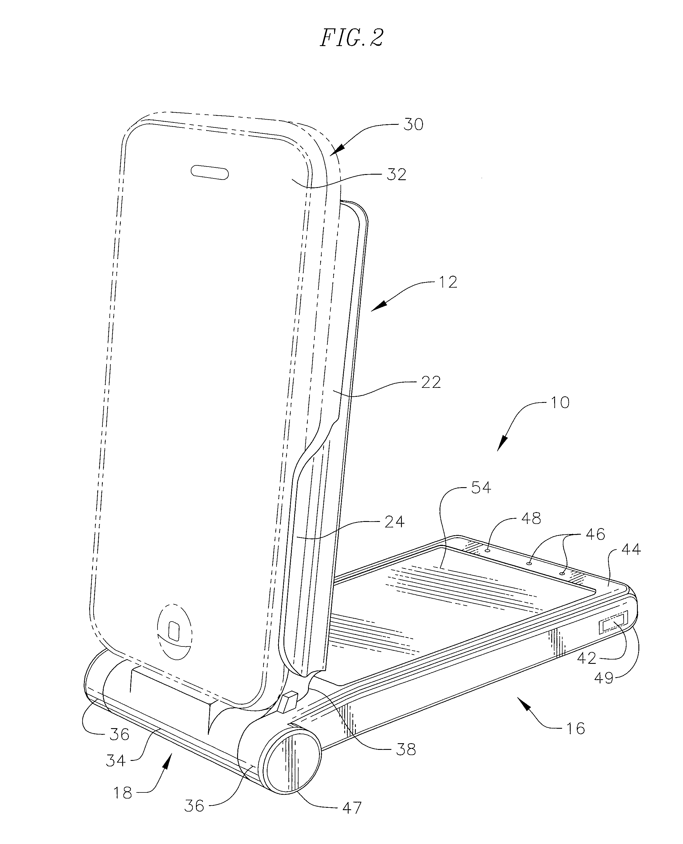
[0016]FIG. 1 is a perspective view showing an exemplary embodiment of the portable phone holder and solar charger 10 of the invention in a partially opened orientation adapted to hold a cellular phone in a slightly tilted back orientation, as shown in FIG. 2. The portable phone holder and solar charger 10 includes a cellular phone cradle portion 12 and an electrical engagement 14, such as electrical jack, which is adapted to electrically connect to a cellular phone or other portable electronic device to be engaged therewith. In cases where the portable phone holder and solar charger 10 is for with devices such as the Apple® brand iPOD® or iTouch® portable phones and MP3 and MP4 players, a 30-pin type of connector jack can be provided. However, the electrical engagement will be selected based on the device to engaged with the portable phone holder and solar charger 10 of the invention. A battery holding base portion 16 is further provided. The battery holding base portion 16 holds a ...


PUM


Abstract

A portable phone holder and solar charger for holding and charging a portable electronic device. The portable phone holder and charger includes a cradle portion which cradles a portable electronic device, a plug or electrical contacts that makes electrical connection with the portable electronic device, a base portion, a battery and recharging electronic circuitry, a solar panel, and a hinge that pivotally connects together the cradle portion and the base portion. The plug is adapted to engage with the portable electronic device and extends from the hinge and moves in concert along with the cradle portion when the base portion and the cradle portion are pivoted relative to each other. The cradle portion retains the portable electronic device in connection with the electrical engagement. The hinge preferably provides click stops at a plurality of positions of pivoting of the cradle portion relative to the base portion. The solar panel allows for recharging of the battery in the base portion to be recharged as well as the connected portable electronic device to be recharged.

Description

CROSS-REFERENCE TO RELATED APPLICATION(S)[0001]This application is a continuation-in-part of prior application Ser. No. 12 / 606,505, filed Oct. 27, 2009, which is a continuation-in-part of prior application Ser. No. 12 / 484,965, filed Jun. 15, 2009.SUMMARY OF THE INVENTION[0002]This invention is related to chargers for portable electronic devices, and more particularly is a portable mobile (cellular) phones and personal digital assistant (PDA) holder and charger having a built in solar charger. Hereinafter, the term portable phone will be used, while it is understood that this term “portable phone” encompasses PDA and other portable electronic devices.[0003]In recent years, hundreds of millions of portable or mobile telephone handsets, aka cellular phones, have been produced and are in use around the world. A consistent problem with cellular phones and PDAs, particularly those that are rich in features, such as internet browsers, video capabilities, texting, music playback and other f...

Claims


Application Information

Patent Timeline
IPC IPC(8): H04W52/00
CPCH02J7/0044H04M1/04H02J7/355H02J7/35
Inventor TAN, QING SONG
Owner TAN QING SONG
Learn More