
Integrated double clips applier with division device for clamping clips

a technology of clamping device and double clip, which is applied in the field of clip applier, can solve the problems of long operating time and inability to easily handle the above-mentioned clip applier, and achieve the effects of reducing operating time, facilitating clamping and cutting, and simplifying the operation steps

Inactive Publication Date: 2010-12-16
CHENG MING HUEI +2
View PDF1 Cites 88 Cited by
  • Summary
  • Abstract
  • Description
  • Claims
  • Application Information

AI Technical Summary

Benefits of technology

[0007]An object of the present invention is to provide a clip applier for clamping ligating clips, which can bring up two ligating clips at the same time and clamp the two clamping positions of the blood vessel with the ligating clips simultaneously in a single step, and thus the operating steps can be simplified, and the time involved with the surgical operation can be shortened.
[0011]After the two clamping positions have been clamped, the advancing unit is moved and enables the cutting unit to move toward the cutting position of the blood vessel to cut the blood vessel at the cutting position. Therefore, an extra step of taking the cutting unit can be eliminated, the cutting steps at the surgical operation can be simplified, and the operation time can be shortened.
[0018]According to the present invention, the first jaw unit may further comprise a first elongation part, the second jaw unit may further comprise a second elongation part, the first elongation part connects to the first end, and the second elongation part connects to the second end. The first elongation part connects to the first end with a first angle, and the second elongation part connects to the second end with a second angle, in which, the first angle and the second angle may independently be 90 to 180 degrees. Preferably, the first angle and the second angle are the same. Therefore, the first jaw unit and the second jaw unit may be both formed in a straight shape or an angled shape as needed. When a blood vessel locates in a deeper position during the surgical operation, the first jaw unit and the second jaw unit with an angled shape may be selectively used for clamping the vessel. Therefore, during the clamping step, the blood vessel can be easily clamped and cut with the end extended from the first elongation part of the jaw unit having an angled shape.
[0019]As mentioned above, the clip applier for clamping ligating clips of the present invention can bring up two ligating clips at the same time and clip the two clamping positions of the blood vessel with the ligating clips simultaneously in a single step, and thus the operating steps can be simplified, and the time involved can be shortened. Besides, the clip applier of the present invention further comprises a cutting unit that can move toward the cutting position of the blood vessel along with the advancing unit to cut the blood vessel. Therefore, compared with the traditional clip applier without a cutting unit, the clip applier of the present invention may enable a step of taking the cutting unit to be eliminated, thereby enabling the cutting steps at the surgery operation to be simplified, and enabling the operation time to be shortened.

Problems solved by technology

Though the clip applier described above is advantageous in its simple structure and is easily manufactured, when applied to the surgical operations, the clip applier described above cannot be easily handled.
However, considering the above method, a lengthy operating time is involved due to the complex steps for the clipping and cutting of the blood vessels, which is restricted with those inconvenient tools.

Method used


Image

  • Integrated double clips applier with division device for clamping clips
  • Integrated double clips applier with division device for clamping clips
  • Integrated double clips applier with division device for clamping clips

Examples


example 1

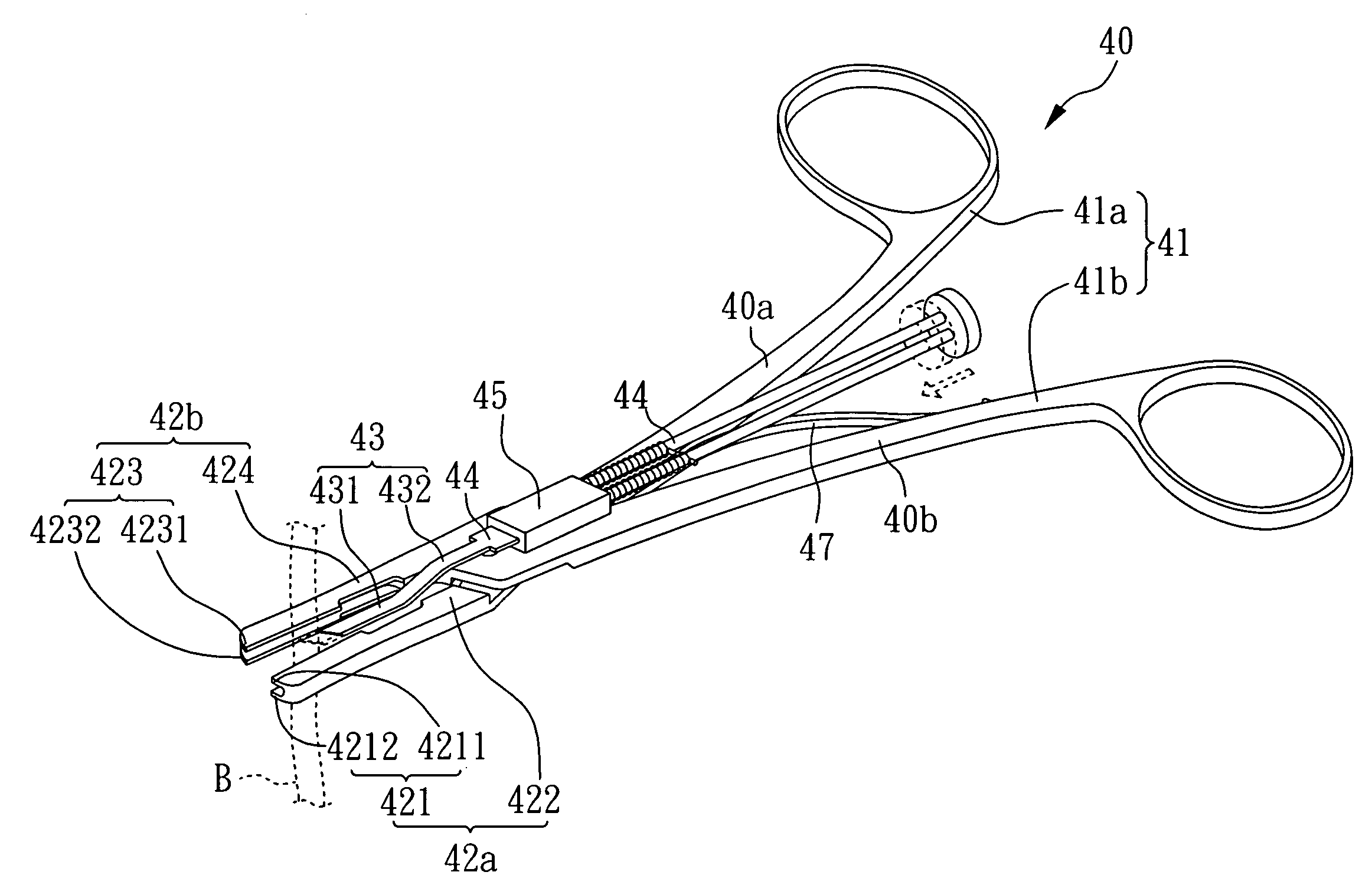
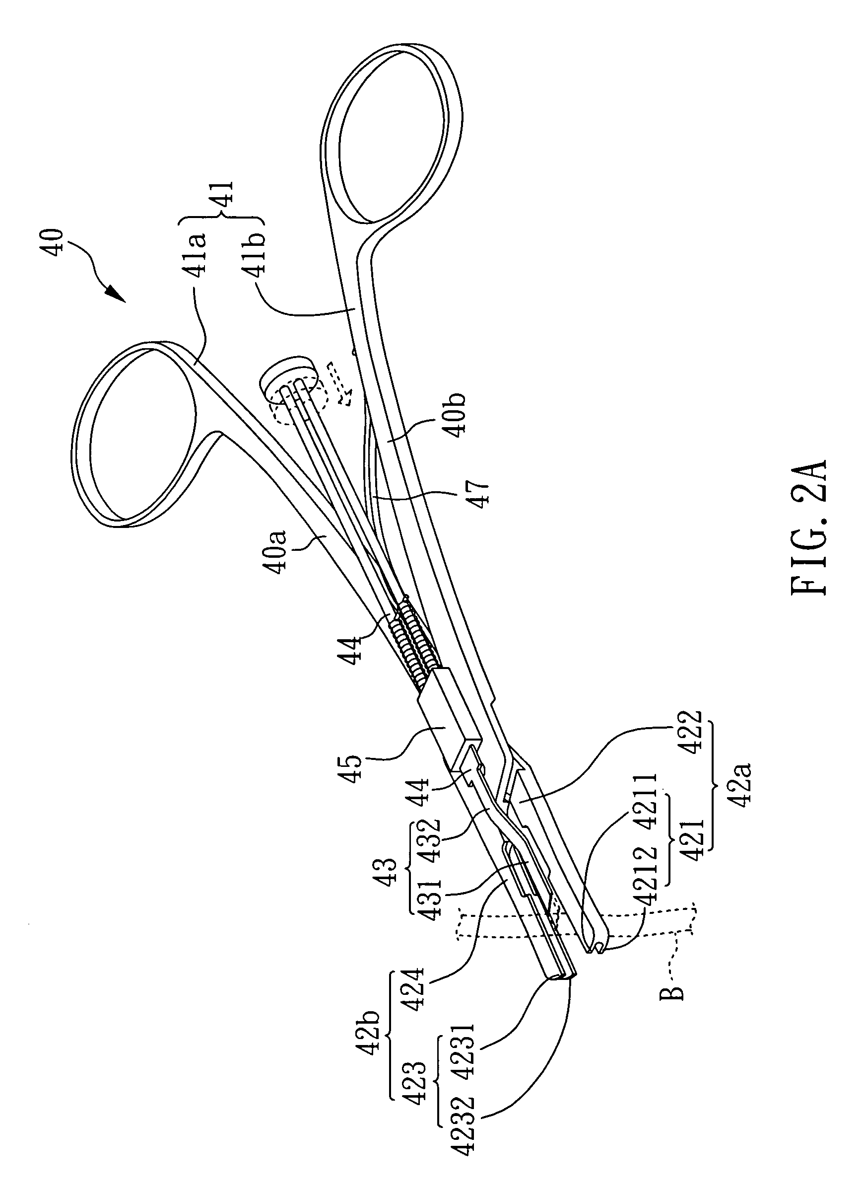
[0035]With reference to FIG. 2A, there is shown a clip applier 40 for clamping ligating clips, which comprises: a handle unit 41; a first jaw unit 42a including a first end 421 and a first elongation part 422, wherein the first end 421 has a first upper clipping portion 4211 and a first lower clipping portion 4212; a second jaw unit 42b including a second end 423 and a second elongation part 424, wherein the second end 423 has a second upper clipping portion 4231 and a second lower clipping portion 4232; a cutting unit 43 having a first cutting component 431 and a first connecting component 432, wherein the first cutting component 431 connects with the first connecting component 432; and an advancing unit 44 connecting with the first connecting component 432 of the cutting unit 43, whereby the cutting unit 43 can be moved by the advancing unit 44.

[0036]Herein, the first end 421 connects to the first elongation part 422 with an angle of 180°; and the second end 423 connects to the se...

example 2

[0042]Referring with FIG. 4, a clip applier 40 for clamping ligating clips of the present example is shown. Except that the cutting component 431 of the cutting unit 43 is a billhook in the present example, the other features and components are the same as those of example 1.

[0043]According to the present example, the clip applier 40 may be utilized in the same steps as shown in FIGS. 3A to 3B. The two clamping positions are clamped in a single step, and then the cutting unit is moved toward the cutting position to cut the blood vessel to complete the cutting process by using the clip applier 40 of the present example.

[0044]Referring with FIG. 4, when the cutting unit 43 moves with the advancing unit 44 toward the cutting position of the blood vessel, the blood vessel may not be cut at the first time due to the elasticity of the blood vessel, and then when the advancing unit 44 moves back to its original position after an applied strength ceases, the blood vessel is cut by the trenc...

example 3

[0045]Referring with FIG. 5, a clip applier 50 for clamping ligating clips of the present example is shown. Except that the cutting unit 53 comprises a first cutting component 531, a first connecting component 532, a second cutting component 533, and a second connecting component 534; the first cutting component 531 connects to the first connecting component 532; the second cutting component 533 connects to the second connecting component 534; and the first connecting component 532 and the second connecting component 534 are pivotally connected in the present example, the other features and components are the same as those of example 1. Moreover, in the present example, the first cutting component 531 and the first connecting component 532 are integrally formed as an elongated arm, and also the second cutting component 533 and the second connecting component 534 are integrally formed as an elongated arm.

[0046]Therefore, the clip applier 50 of the present example may be utilized (ope...


PUM


Abstract

The present invention relates to a clip applier for clipping and dividing blood vessels, including: a handle; a first jaw unit; and a second jaw unit. The clip applier of the present invention can bring up two ligating clips at the same time with the first jaw unit and the second jaw unit, whereas the two clamping positions of the blood vessel can be clamped with the ligating clips simultaneously by the clip applier of the present invention in a single step, and thus the operating steps can be simplified, and the time involved with the surgical operation can be shortened.

Description

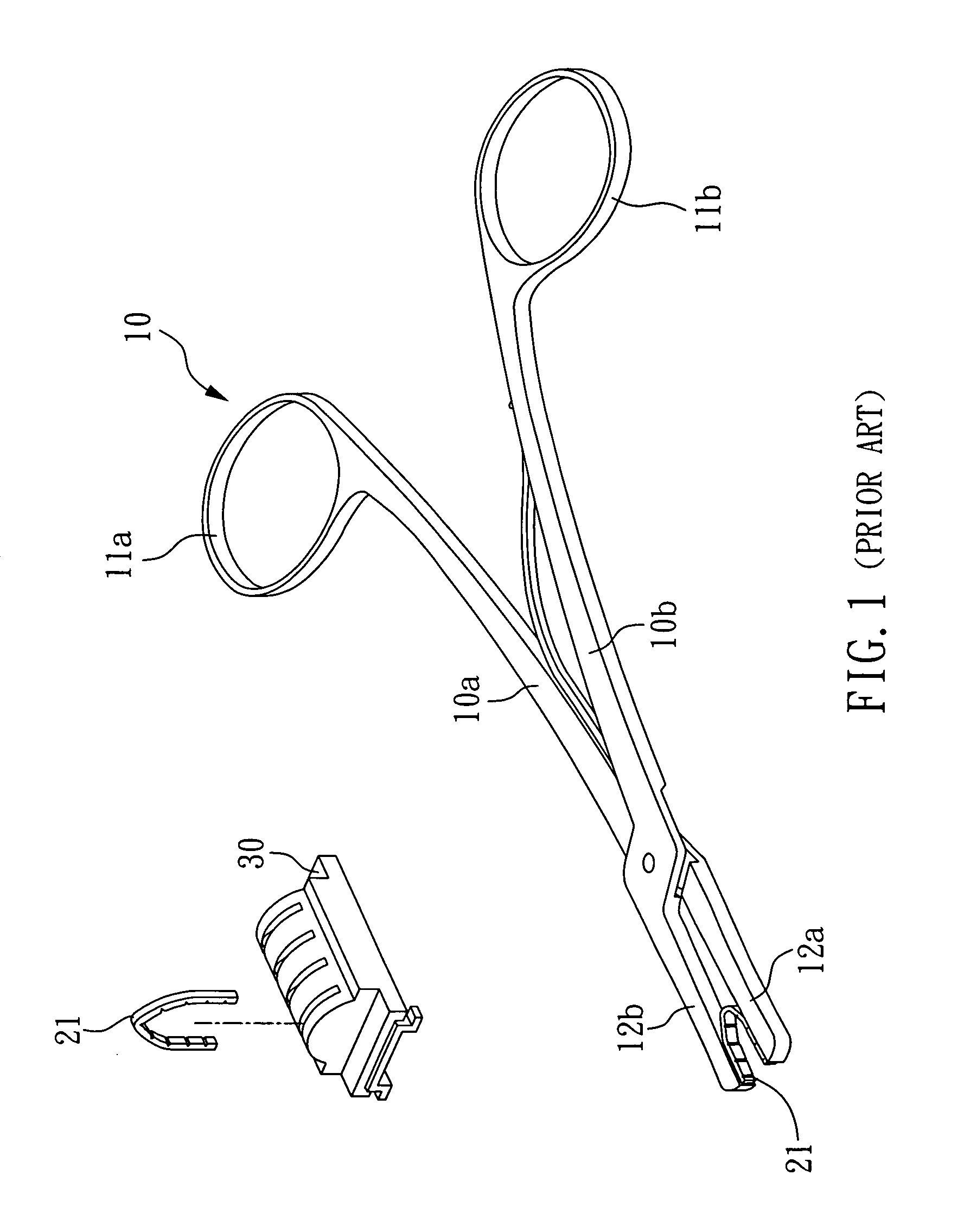
BACKGROUND OF THE INVENTION[0001]1. Field of the Invention[0002]The present invention relates to a clip applier and, more particularly, to a clip applier for clamping one or more ligating clips simultaneously.[0003]2. Description of Related Art[0004]During a surgical operation, a temporary ligating of the blood vessels is usually applied to prevent bleeding of blood vessels, and some tools for such operations have been developed to assist the ligation of the blood vessels. Commonly, for example, a clip applier is used first to pick up a ligating clip, and then blood vessels are ligated by the ligating clip upon the ligating clip being clipped / deformed by the clip applier.[0005]Reference with FIG. 1, a conventional clip applier 10 for clamping ligating clips is shown, which comprises: a first clip unit 10a having a first handle 11a at one end and a first jaw unit 12a at another end; and a second clip unit 10b having a second handle lib at one end and a second jaw unit 12b at another ...

Claims


Application Information

Patent Timeline
Patent Type & Authority Applications(United States)
IPC IPC(8): A61B17/10
CPCA61B17/1222A61B17/128A61B2017/1225A61B2017/00353A61B2017/00477A61B17/32
Inventor CHENG, MING-HUEIHENRY, STEVE L.
Owner CHENG MING HUEI
Learn More