Small engine emissions control valve

a technology for reducing emissions and valves, which is applied in the direction of lighting and heating apparatus, heating types, applications, etc., can solve the problems of liquid still escaping through the valve assembly, gravity feed systems cannot operate under vacuum conditions,

Active Publication Date: 2010-12-23
EATON INTELLIGENT POWER LTD
View PDF27 Cites 46 Cited by
  • Summary
  • Abstract
  • Description
  • Claims
  • Application Information

AI Technical Summary

Benefits of technology

[0004]A valve assembly for a fuel tank for a small engine is provided. The valve assembly includes a housing. The housing defines a housing cavity and a vapor opening. The vapor opening allows vapor to enter the housing cavity from the fuel tank. A vapor outlet is also defined by the housing and allows the vapor to exit the housing cavity. A membrane is supported by the housing below the vapor opening such that the vapor must flow through the membrane to reach the vapor cavity. The membrane allows the passage of vapor and prevents the passage of liquid through the membrane. A pressure relief valve is supported by the housing to assist in controlling vapor flow through the housing.

Problems solved by technology

However, gravity feed systems will not operate under vacuum conditions.
Therefore, some liquid may still escape through the valve assemblies due to sloshing of the liquid during normal fuel tank usage.

Method used


Image

  • Small engine emissions control valve
  • Small engine emissions control valve
  • Small engine emissions control valve

Examples


second embodiment

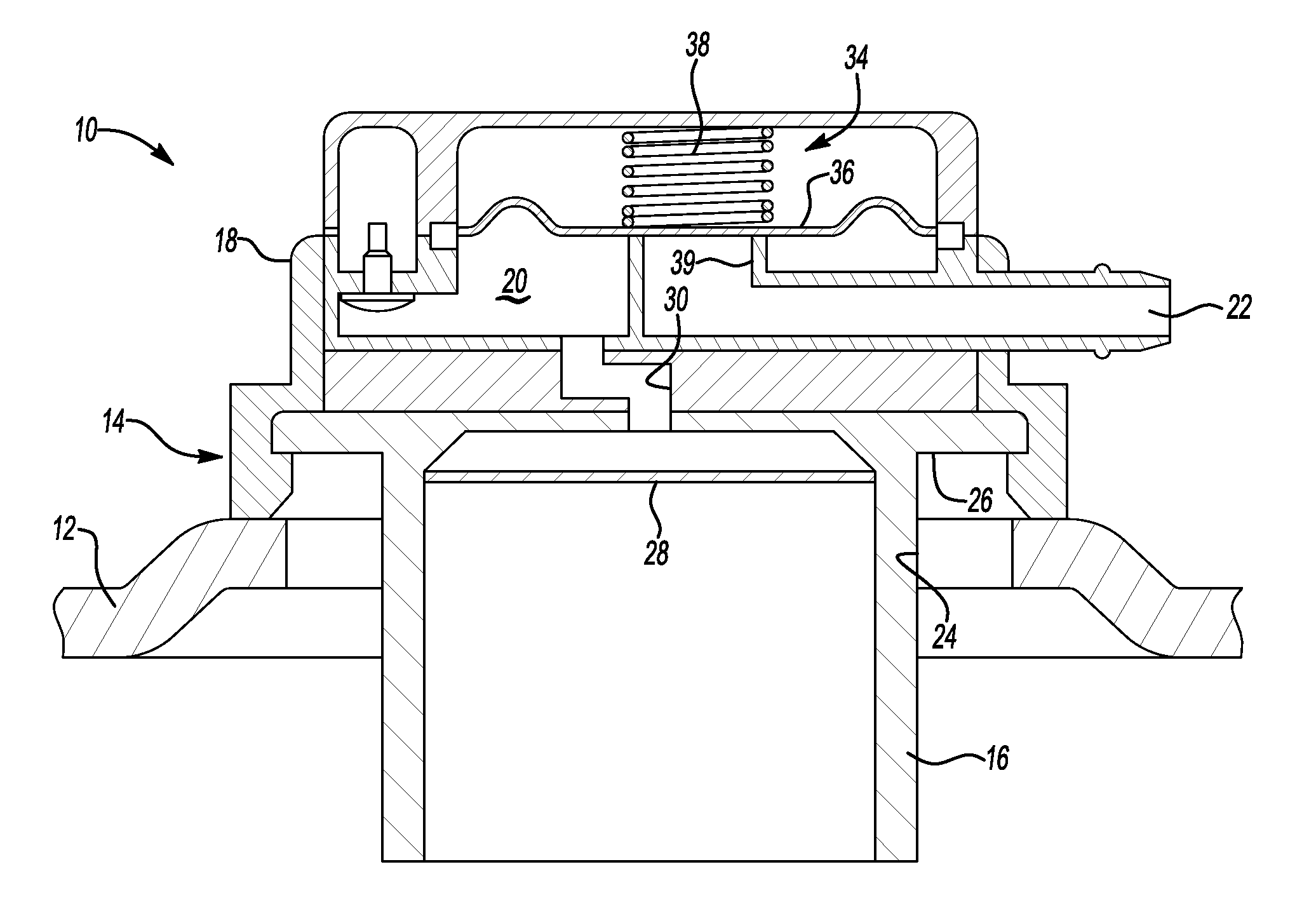
[0026]FIG. 2 illustrates a valve assembly 110 having a membrane 128 for use with a fuel tank 112. The valve assembly 110 is for use with a fuel tank 112 for a small engine. The valve assembly 110 has a housing 114. The housing 114 is mounted externally of the fuel tank 112. The embodiment shown illustrates the valve assembly 110 mounted directly to the fuel tank 112. Other arrangements for mounting the valve assembly 110 to the fuel tank 112 or incorporating the valve assembly 110 into other components prior to mounting on the fuel tank 112 may also be used. One skilled in the art would know the desired arrangements for particular fuel tank 112 and valve assembly 110 combinations.

[0027]The fuel tank 112 defines a fuel tank opening 140, which allows vapor to exit the fuel tank 112. The housing 114 also defines a housing cavity 120, also referred to as a vent opening, which is in fluid communication with a vapor outlet 122.

[0028]A membrane 128 is secured to the housing 114. The membra...

third embodiment

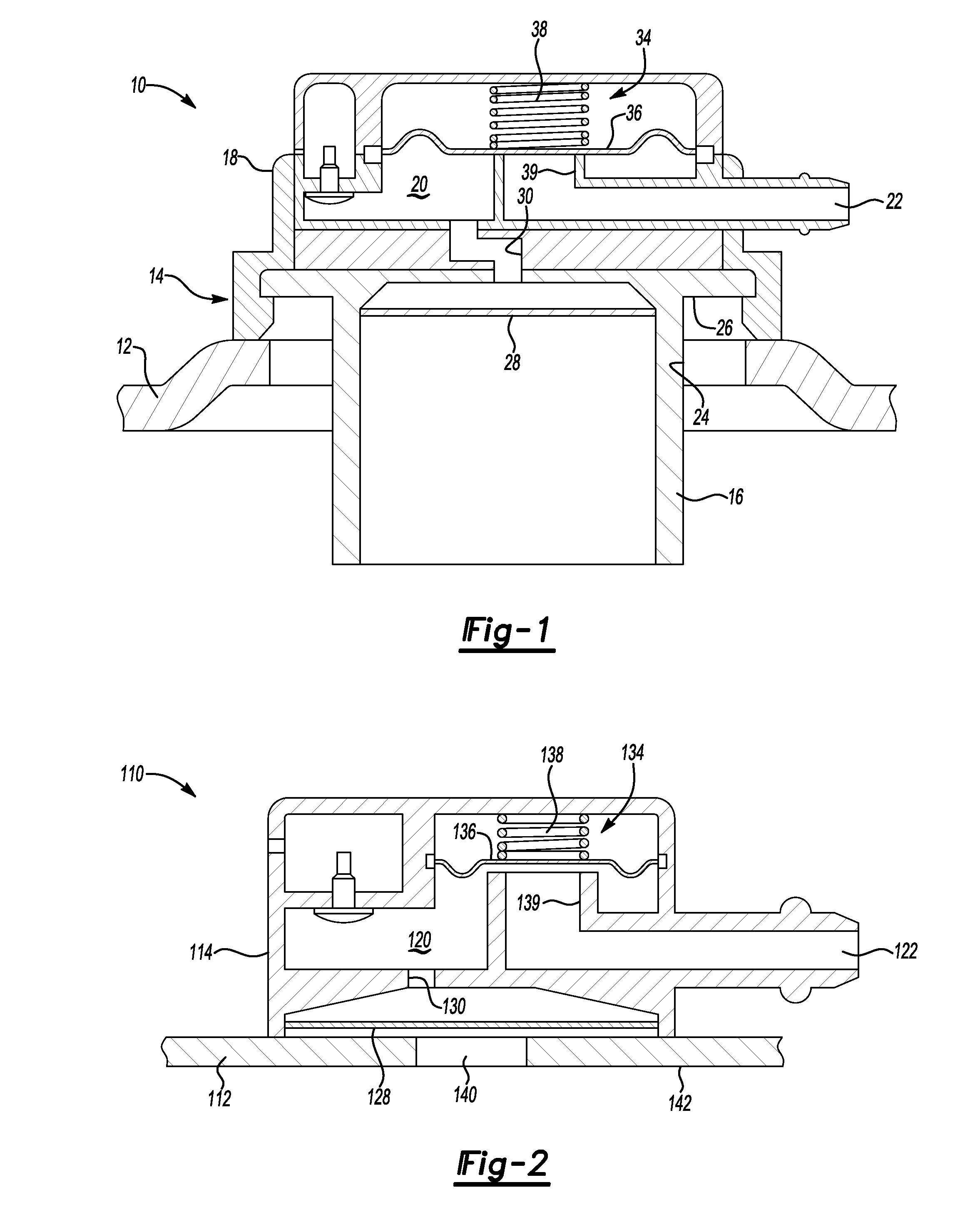
[0034]FIG. 3 illustrates the valve assembly 210 mounted to a fuel tank 212. The valve assembly 210 is for use with a fuel tank 212 for a small engine. The valve assembly 210 has a housing 214. The housing 214 is mounted externally of the fuel tank 212. The embodiment shown illustrates the valve assembly 210 mounted directly to the fuel tank 212. Other arrangements for mounting the valve assembly 210 to the fuel tank 212, or incorporating the valve assembly 210 into other components prior to mounting on the fuel tank 212 may also be utilized. One skilled in the art would know the desired arrangements for particular fuel tank 212 and valve assembly 210 combinations.

[0035]The fuel tank 212 defines a fuel tank opening 240 that allows vapor to exit the fuel tank 212. The housing 214 also defines a housing cavity 220, also referred to as a vent opening, which is in fluid communication with a vapor outlet 222.

[0036]A membrane 228 is secured to the housing 214. The membrane 228 may be secur...

fourth embodiment

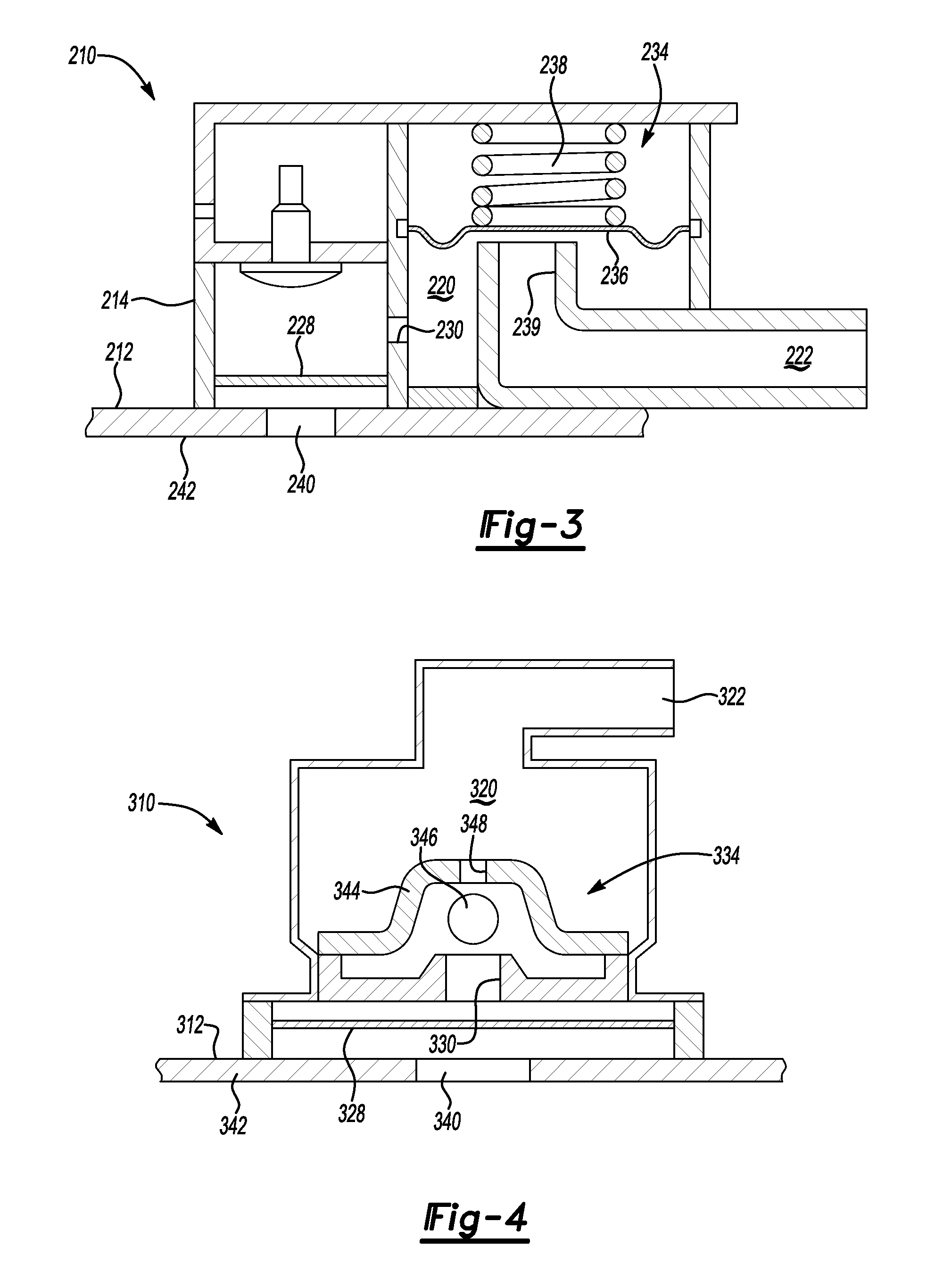
[0042]FIG. 4 illustrates the valve assembly 310 mounted to a fuel tank 312. The valve assembly 310 is for use with a fuel tank 312 for a small engine. The valve assembly 310 has a housing 314. The housing 314 is mounted externally of the fuel tank 312. The embodiment shown illustrates the valve assembly 310 mounted directly to the fuel tank 312. Other arrangements for mounting the valve assembly 310 to the fuel tank 312, or incorporating the valve assembly 310 into other components prior to mounting on the fuel tank 312 may also be utilized. One skilled in the art would know the desired arrangements for particular fuel tank 312 and valve assembly 310 combinations.

[0043]The fuel tank 312 defines a fuel tank opening 340, which allows vapor to exit the fuel tank 312. The housing 314 also defines a housing cavity 320, also referred to as a vent opening, which is in fluid communication with a vapor outlet 322.

[0044]A membrane 328 is secured to the housing 314. The membrane 328 may be sec...


PUM


Abstract

A valve assembly for a fuel tank for a small engine includes a housing. A membrane is supported by the housing such that the membrane covers a housing opening. The membrane allows the passage of vapor through the membrane and into the housing cavity and prevents the passage of liquid through the membrane. A pressure relief valve is supported by the housing to control flow of a vapor through the housing cavity.

Description

TECHNICAL FIELD[0001]The invention relates to a valve assembly, and more particularly, to a liquid discriminating valve assembly for a fuel tank for a small engine.BACKGROUND OF THE INVENTION[0002]Valve assemblies to control the fluid level and vapor flow for fuel tanks are known. Fuel tanks used with small engines commonly work on a gravity feed system to transmit the fuel to the engine. With gravity feed systems, maintaining some pressure within the fuel tank is desirable. However, gravity feed systems will not operate under vacuum conditions. Thus, the valve assemblies must be able to vent vapor within the fuel tank and maintain the pressure level within the fuel tank. As is known, the vapor is typically vented into the intake line for the engine. Additionally, these valve assemblies will also vent vapor to maintain pressure within the fuel tank as a result of changes in the fuel level.[0003]Rollover valves are installed in the fuel tanks to prevent the liquid from reaching the v...

Claims


Application Information

Patent Timeline
Patent Type & Authority Applications(United States)
IPC IPC(8): F16K24/04
CPCB60K15/03504F02M25/0836F02M37/007B60K15/03519F16K24/04B60K2015/03276F02M37/20Y10T137/3084Y10T137/3087Y10T137/3099Y10T137/86292B60K15/035F02M25/08F02M37/00
Inventor ERDMANN, MATTHEW LORENZMILLS, VAUGHN KEVIN
Owner EATON INTELLIGENT POWER LTD
Why Eureka
Try Eureka