Downhole tool leg retention methods and apparatus

a technology of leg retention and downhole drilling, which is applied in the direction of shaft sinking, shaft equipment, manufacturing tools, etc., can solve the problems of leg movement within the receptacle, methodological cost prohibitive or otherwise inappropriate, etc., and achieve the effect of restricting the radial movement of the cutting leg assembly

Active Publication Date: 2010-12-23
SANDVIK INTELLECTUAL PROPERTY AB
View PDF3 Cites 21 Cited by
  • Summary
  • Abstract
  • Description
  • Claims
  • Application Information

AI Technical Summary

Benefits of technology

[0010]In one aspect, embodiments disclosed herein relate to a back reamer including a drive stem configured to support a main reamer body, the main reamer body including a plurality of receptacles, and a plurality of cutting leg assemblies in positive locking engagement with the plurality of receptacles to restrict radial movement of the cutting leg assemblies.

Problems solved by technology

Frequently, HDD bores are drilled to traverse rivers, roadways, buildings, or any other structures where a “cut and cover” methodology is cost prohibitive or otherwise inappropriate.
Additionally, dead weight of the entire reamer (some reamers may weight up to 12,000 pounds or more) during each revolution and vibrations during operation combine to form a dynamic load “D,” which causes leg movement within the receptacles.

Method used


Image

  • Downhole tool leg retention methods and apparatus
  • Downhole tool leg retention methods and apparatus
  • Downhole tool leg retention methods and apparatus

Examples


Embodiment Construction

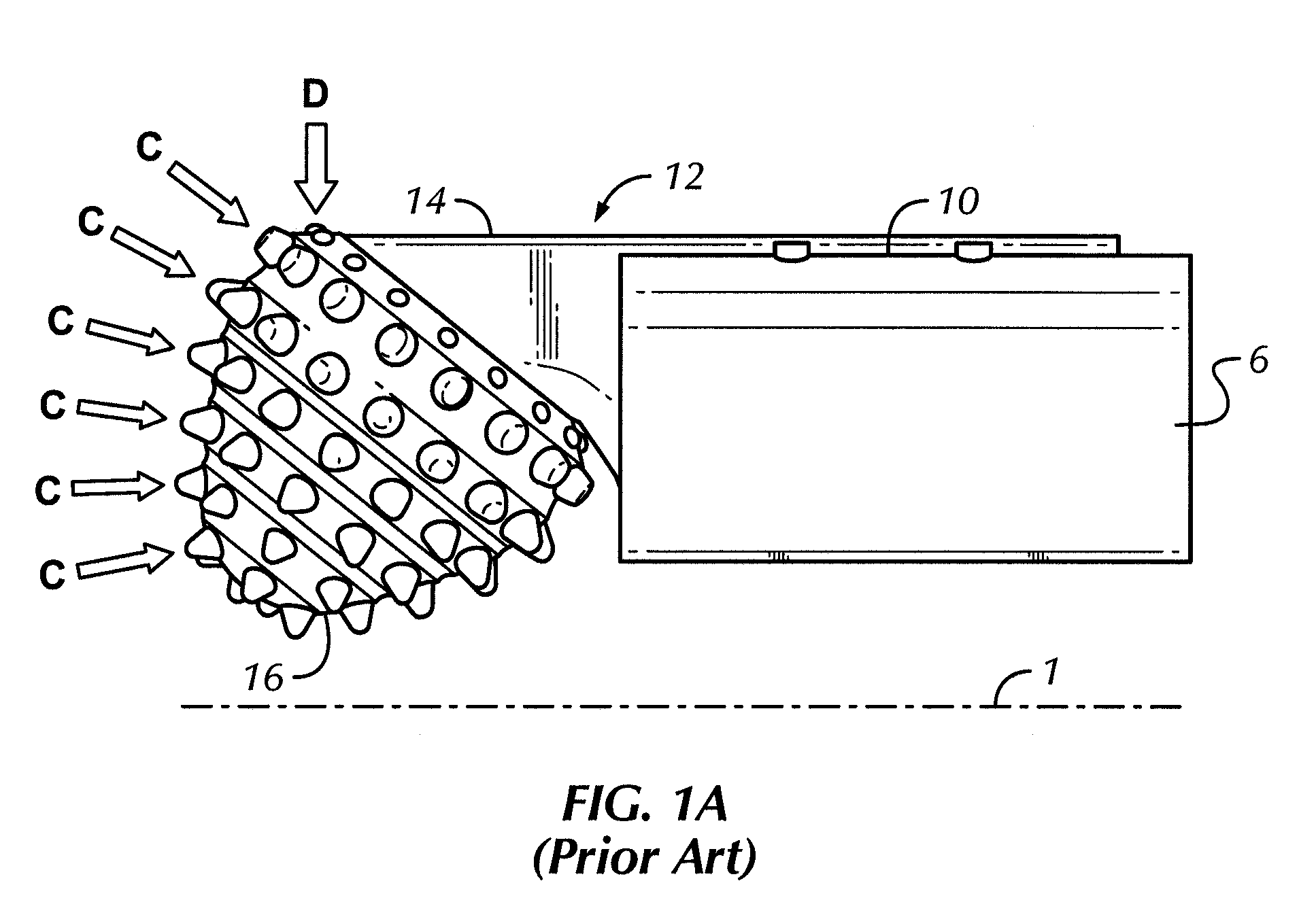
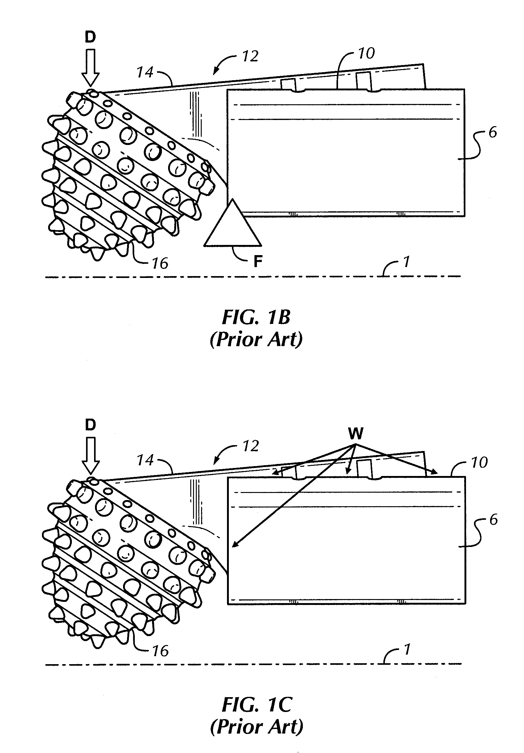
[0027]Embodiments disclosed herein relate to a back reamer assembly for use in drilling. In particular, embodiments disclosed herein relate to methods and apparatus providing positive locking engagements between cutting leg assemblies and receptacles of a main reamer body to prevent radial movement of the cutting leg assemblies within the receptacles of the main reamer body.

[0028]Referring initially to FIGS. 2 and 3 together, a back reamer assembly 100 is shown. FIG. 2 depicts back reamer assembly 100 in an assembled state and FIG. 3 depicts back reamer assembly 100 in an exploded state. Back reamer 100 has a central axis 101, and as shown, includes a drive stem 102 upon which a support plate 104, a main reamer body 106, and a centralizer 108 are mounted. Main reamer body 106, positioned between support plate 104 and centralizer 108, includes a plurality of receptacles 110, in which a plurality of cutting leg assemblies 112 are mounted. Main reamer body 106 may be a fabricated body,...


PUM


Abstract

A back reamer includes a drive stem configured to support a main reamer body, the main reamer body including a plurality of receptacles, and a plurality of cutting leg assemblies in positive locking engagement with the plurality of receptacles to restrict radial movement of the cutting leg assemblies.

Description

BACKGROUND[0001]1. Field of the Disclosure[0002]Embodiments of the present disclosure relate generally to horizontal directional drilling reamers. More particularly, embodiments of the present disclosure relate to methods and apparatus to minimize movement of cutting leg assemblies mounted on directional drilling reamers.[0003]2. Background Art[0004]Horizontal directional drilling (“HDD”) is a process through which a subterranean bore is directionally drilled in a substantially horizontal trajectory from one surface location to another. Typically, HDD operations are used by the utilities industry to create subterranean utility conduits underneath pre-existing structures, but any application requiring a substantially horizontal borehole may utilize HDD. Frequently, HDD bores are drilled to traverse rivers, roadways, buildings, or any other structures where a “cut and cover” methodology is cost prohibitive or otherwise inappropriate.[0005]During a typical HDD operation, a horizontal d...

Claims


Application Information

Patent Timeline
Patent Type & Authority Applications(United States)
IPC IPC(8): E21B7/28E21B10/26B21K5/04
CPCE21B10/28E21B7/28
Inventor BHOME, AMOLSLAUGHTER, JR., ROBERT H.
Owner SANDVIK INTELLECTUAL PROPERTY AB
Why Eureka
Try Eureka