Electric linear motion actuator and electric brake assembly

a technology of linear motion and actuator, which is applied in the direction of fluid actuated brakes, gearing, transportation and packaging, etc., can solve the problems of pushing up manufacturing costs, and achieve the effect of stably transmitting the torque of the rotary sha

Inactive Publication Date: 2010-12-23
NTN CORP
View PDF10 Cites 39 Cited by
  • Summary
  • Abstract
  • Description
  • Claims
  • Application Information

AI Technical Summary

Benefits of technology

[0024]Since the electric linear motion actuator according to the present invention includes elastic members biasing and pressing the respective planetary rollers against the radially outer surface of the rotary shaft, it is possible to stably transm

Problems solved by technology

Thus, additional time is necessary for the steps of finishing the rotary shaft and the oute

Method used


Image

  • Electric linear motion actuator and electric brake assembly
  • Electric linear motion actuator and electric brake assembly
  • Electric linear motion actuator and electric brake assembly

Examples


Embodiment Construction

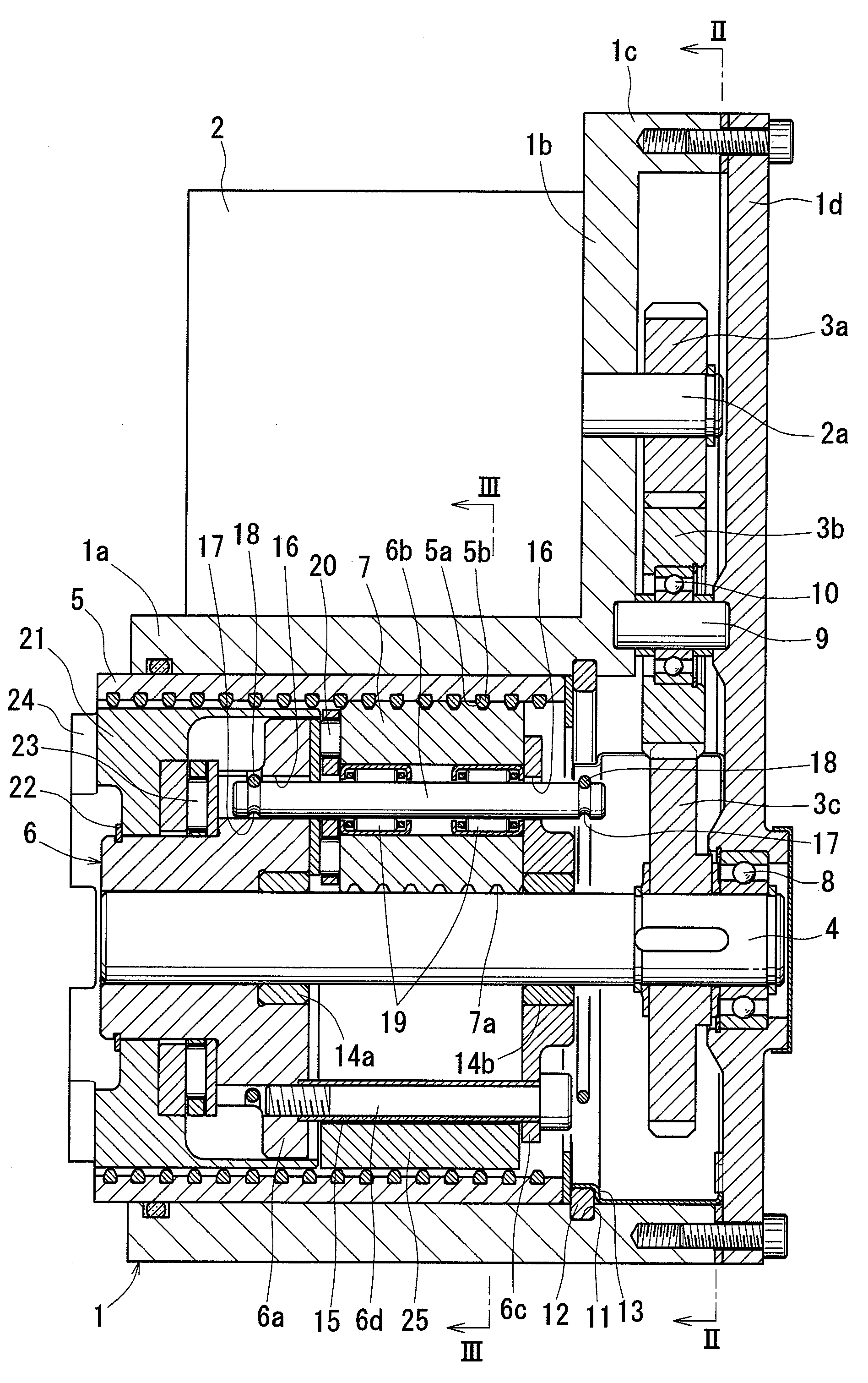
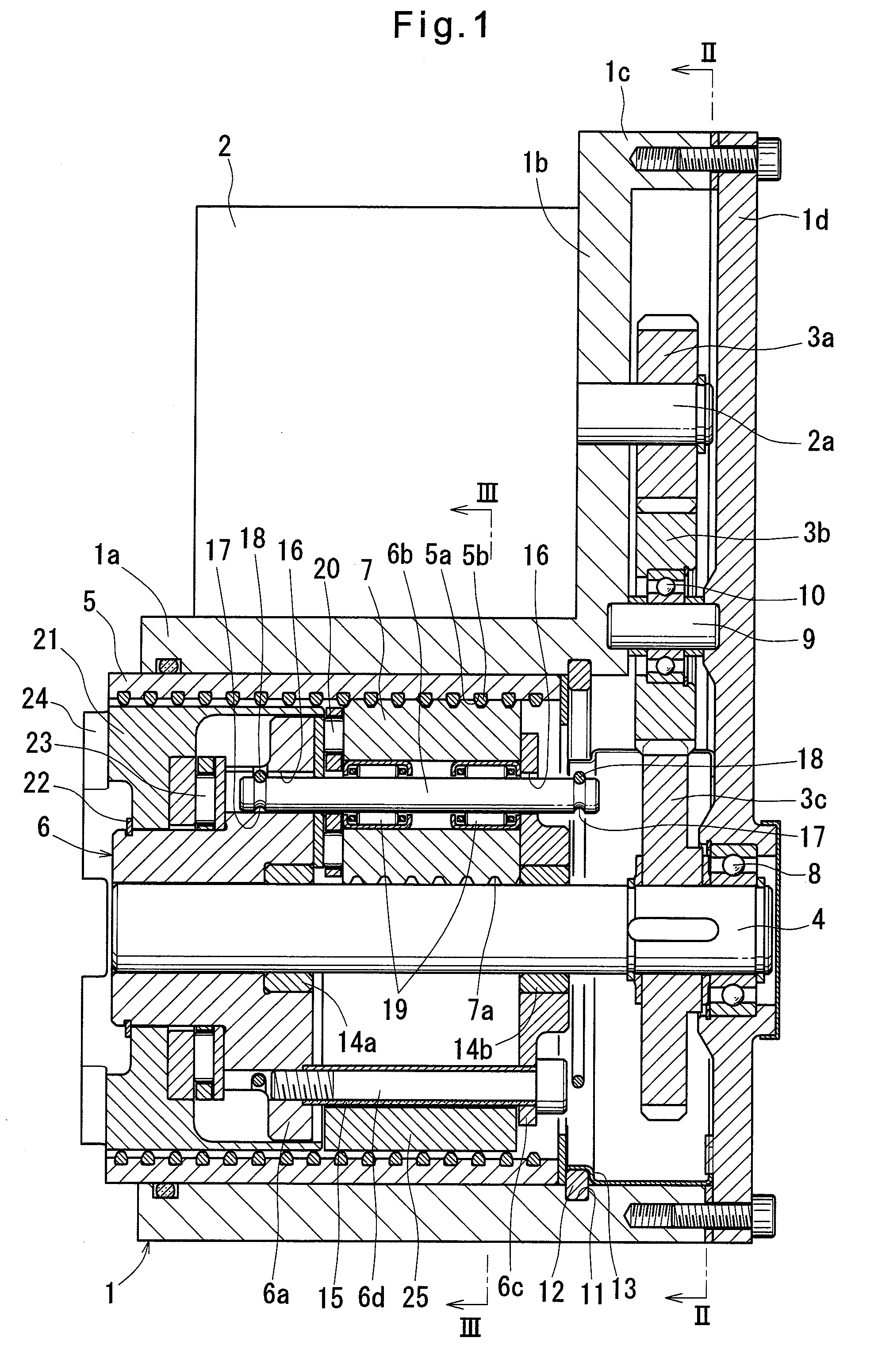
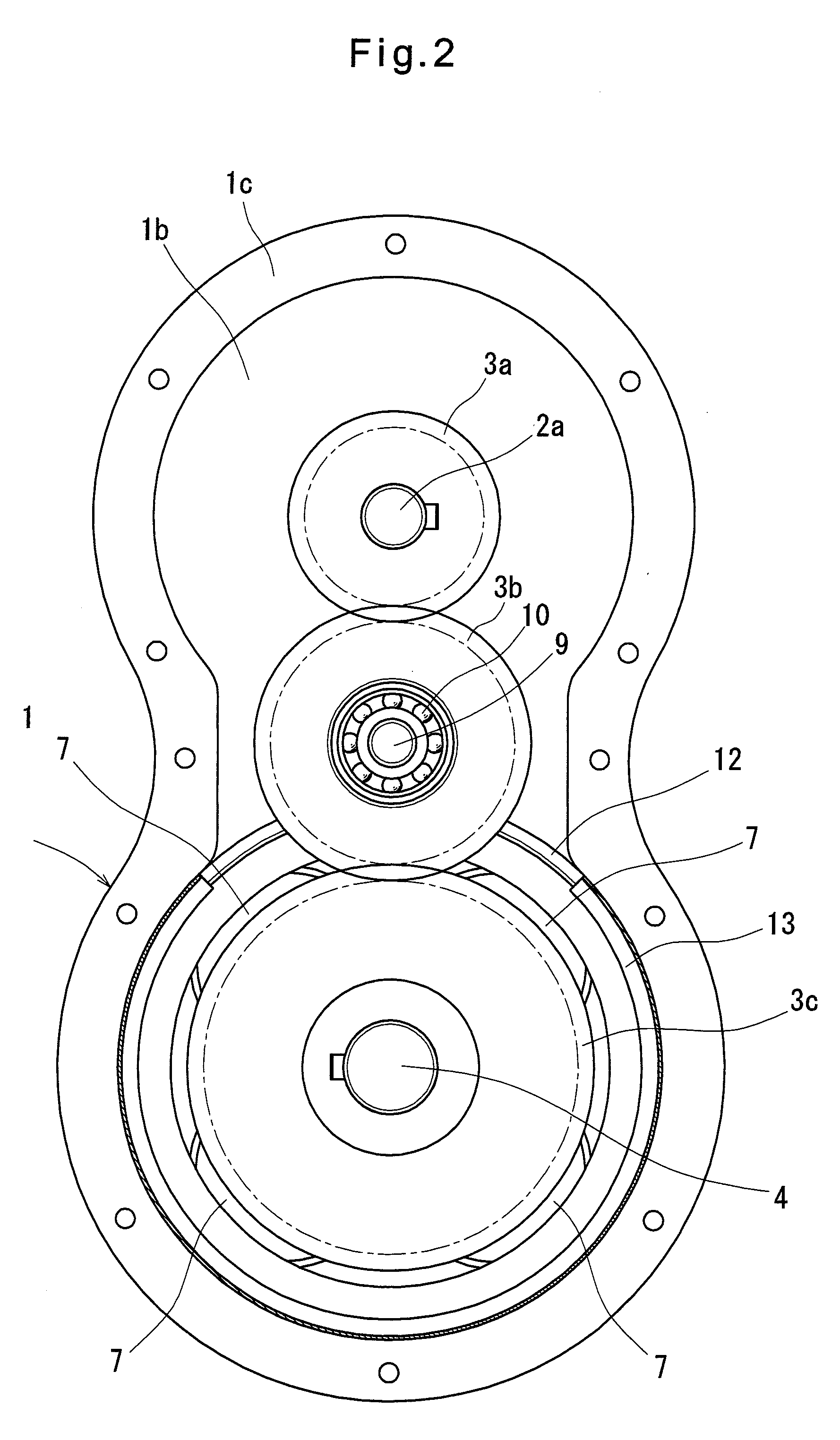
[0080]Now the embodiments of the present invention are described with reference to the drawings. FIGS. 1 to 6 show the first embodiment. As shown in FIGS. 1 to 3, the electric linear motion actuator of this embodiment includes a casing 1 comprising a cylindrical portion 1a and an hourglass-shaped flange 16 protruding from one end of the cylindrical portion 1a. An electric motor 2 is mounted to the flange 1b in parallel to the cylindrical portion 1a. The electric motor 2 has an rotor shaft 2a which is configured such that its rotation is transmitted to a rotary shaft 4 extending along the axis of the cylindrical portion 1a through gears 3a, 3b and 3c. Four planetary rollers 7 rotatably supported by a carrier 6 are disposed between the rotary shaft 4 and an outer ring member 5 fixed to the radially inner surface of the cylindrical portion 1a. When the rotary shaft 4 rotates, the respective planetary rollers 7 are configured to revolve around the rotary shaft 4, while rotating about th...


PUM


Abstract

An object is to make it possible to stably transmit torque of the rotary shaft to the respective planetary rollers without applying a preload to the planetary rollers with a negative gap between the radially outer surface of the rotary shaft and the radially inner surface of the outer ring member.
Planetary rollers 7 rotatably supported on their radially inner surfaces by respective support pins 6b are radially inwardly biased by radially compressible ring springs 18 enveloping the support pins 6b, thereby biasing and pressing the respective planetary rollers 7 against the radially outer surface of a rotary shaft 4. Thus, it is possible to stably transmit torque of the rotary shaft 4 to the respective planetary rollers 7 without applying a preload to the planetary rollers 7 with a negative gap between the radially outer surface of the rotary shaft 4 and the radially inner surface of the outer ring member 5.

Description

TECHNICAL FIELD[0001]The present invention relates to an electric linear motion actuator for converting rotary motion of an electric motor to linear motion, thereby linearly driving a driven member, and an electric brake assembly for pressing a brake member against a member to be braked using the electric linear motion actuator.BACKGROUND ART[0002]Typically, electric linear motion actuators for converting rotary motion of an electric motor to linear motion, thereby linearly driving a driven member use a ball-screw mechanism or a ball-ramp mechanism. Also, in order to produce a large linear driving force with a small-capacity electric motor, a gear reduction mechanism such as a planetary gear reduction mechanism is often used (see e.g. Patent document 1).[0003]While ball-screw mechanisms or ball-ramp mechanisms as used in electric linear motion actuators can amplify force to a certain extent with its motion converter mechanism due to threads having a lead or inclined cam surfaces. Bu...

Claims


Application Information

Patent Timeline
IPC IPC(8): F16H25/22F16H25/18F16D65/16F16D65/34F16D65/28
CPCF16H25/2252F16D2121/24F16D2125/40F16D2125/48F16D2125/50Y10T74/18568F16D65/18
Inventor YAMASAKI, TATSUYAEGUCHI, MASAAKIYAMAGUCHI, KATSUHISAMAKINO, TOMOAKI
Owner NTN CORP
Why Eureka
Try Eureka