
Vehicle door latch with motion restriction device prohibiting rapid movement of opening lever

a technology of a restriction device and an opening lever, which is applied in the direction of lock applications, carpet fasteners, mechanical devices, etc., can solve the problems of unintentional force acting on the latch system, affecting the safety of the vehicle, and causing the vehicle to fling open

Inactive Publication Date: 2010-12-23
MAGNA CLOSURES INC
View PDF21 Cites 27 Cited by
  • Summary
  • Abstract
  • Description
  • Claims
  • Application Information

AI Technical Summary

Benefits of technology

[0007]In a preferred embodiment, the motion restriction device is coupled to an auxiliary pawl that is connected to the pawl of a ratchet and pawl combination. The auxiliary pawl must be actuated by one or more release levers in order to actuate the pawl and release the ratchet from a striker-containing position and open the latch. By coupling the motion restriction device to a lever located close to the pawl, it is possible to target release motion that originates from a variety of sources within the latch system. In addition, because the only criterion for selectively prohibiting movement of the auxiliary pawl is its speed, it is possible to prevent the latch from unintentionally opening regardless of the direction the inertial forces are applied to door handles, latch or the release levers therein.
[0009]In the preferred embodiment, the auxiliary pawl is coupled to the motion restriction in such a manner that the angular speed of the auxiliary pawl is amplified when applied to the motion restriction device, to increase the speed of a moveable part of the motion restriction device.

Problems solved by technology

It is possible in a vehicle crash situation that the impact resulting from the crash could have a deleterious effect on any part of the vehicle door latch system, which is intended to keep the vehicle door latched to the vehicle body.
However, in a crash, particularly in a roll-over situation where the door latch may be subjected to inertial forces directed over a wide angular range in three dimensions, the forces acting on the latch system may unintentionally actuate one or more latch system levers (which can be relatively long and have centers of mass located far from the rotation axis) and consecutively act to open the door latch.
Needless to say, it is highly undesirable to have the vehicle door fling open in a crash situation, especially in a rollover.
However, one of the limitations of that system is that the counterweight is actuated only by inertial forces acting along a relatively narrow angular range.

Method used


Image

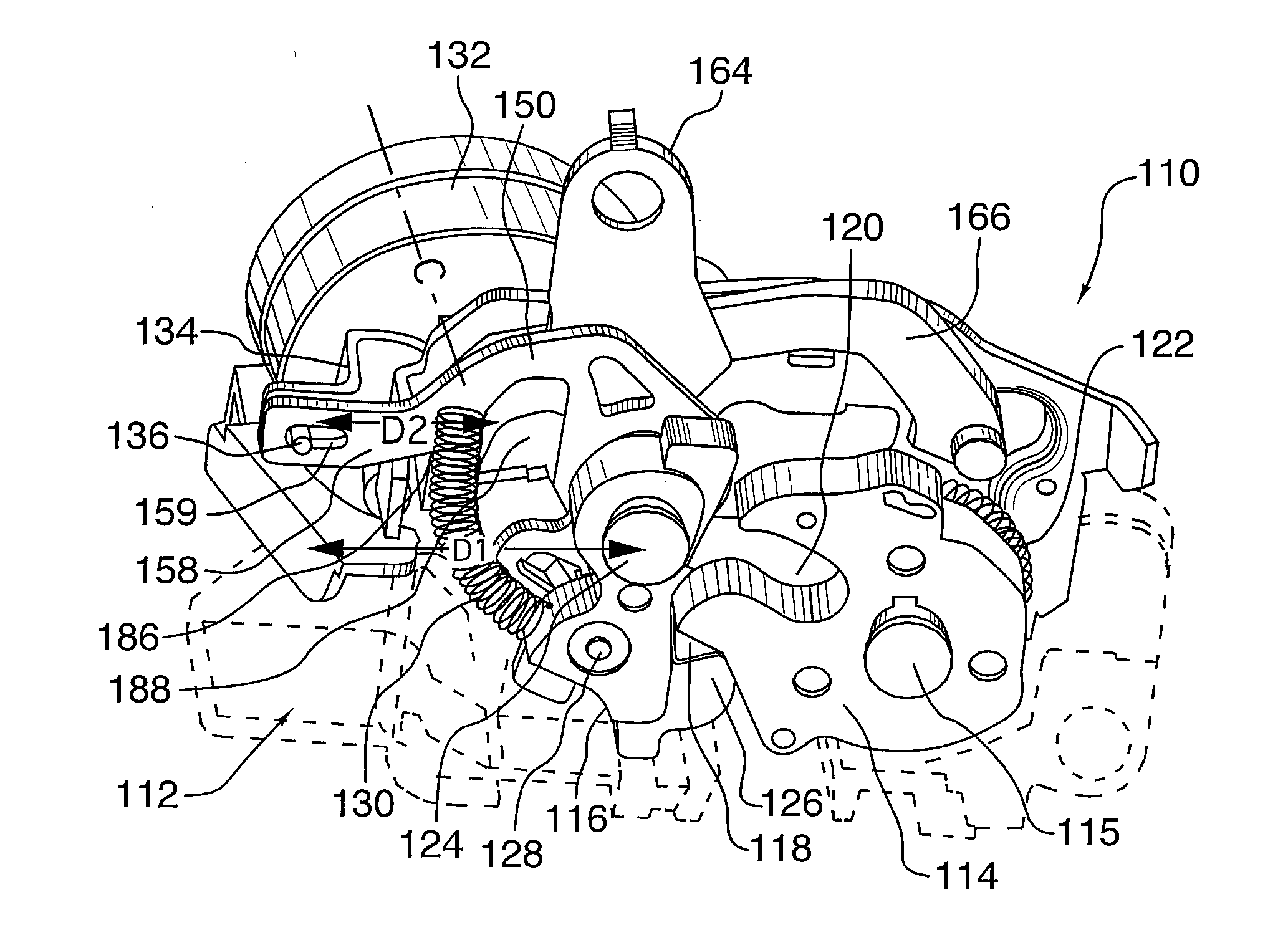
  • Vehicle door latch with motion restriction device prohibiting rapid movement of opening lever
  • Vehicle door latch with motion restriction device prohibiting rapid movement of opening lever
  • Vehicle door latch with motion restriction device prohibiting rapid movement of opening lever

Examples


Embodiment Construction

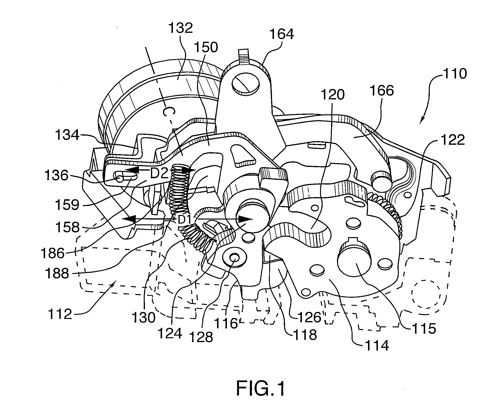
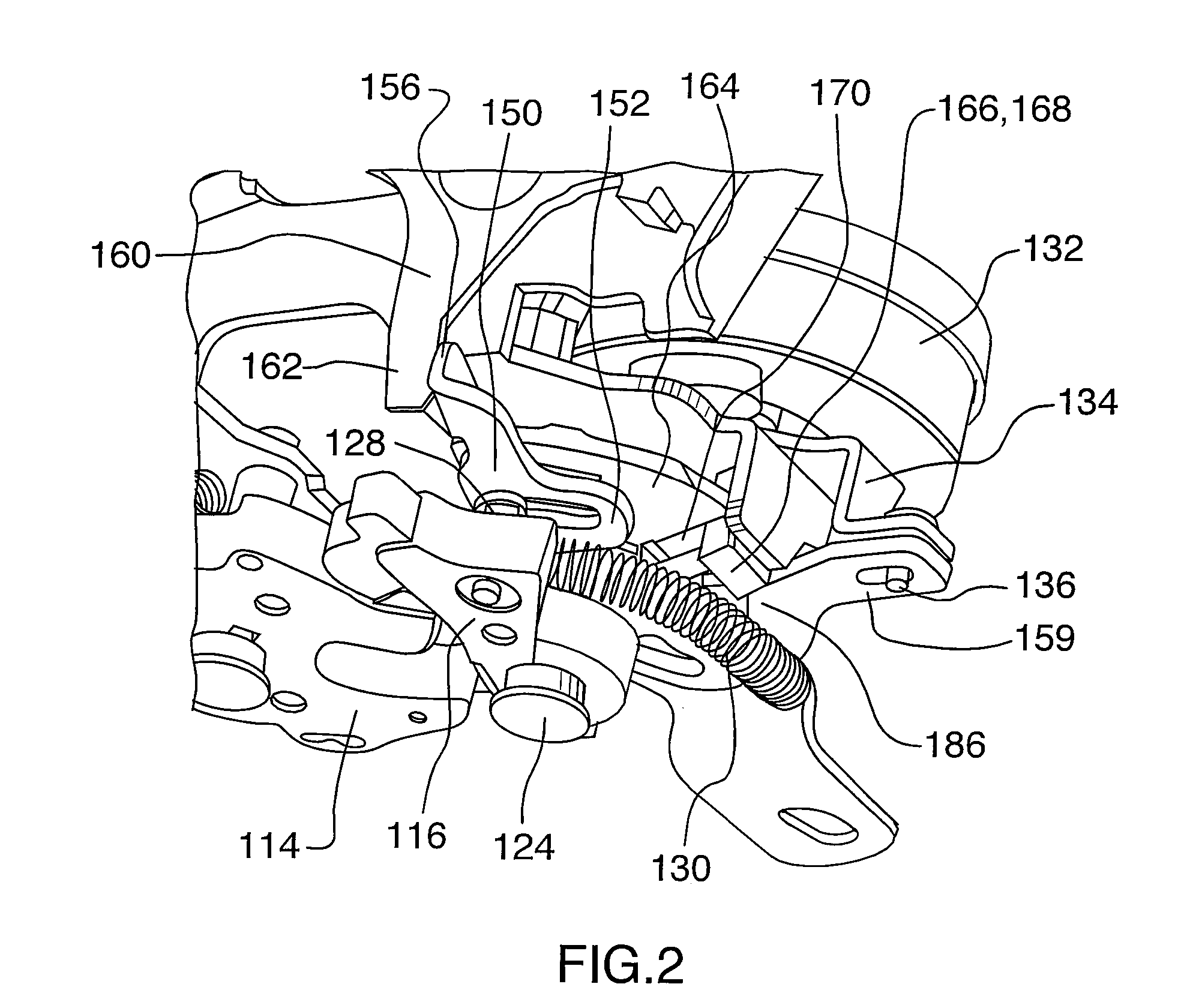
[0027]Referring to FIGS. 1 through 3, a door latch assembly, generally shown at 110, includes a housing 112 (shown in phantom as the details thereof are not important to understanding the invention) adapted to be attached to a motor vehicle door. The motor vehicle door may be, but is not limited to, a side door, a liftgate, a hood, a decklid, a sliding door, or a cargo door.

[0028]A first member or ratchet 114 and a second member or pawl 116 each are rotatably mounted to the housing 112. The ratchet 114 includes a shoulder 118 and defines an opening 120. The ratchet 114 is movable between a latched position, shown in FIG. 1, in which a striker (not shown) positioned along a motor vehicle body is retained within the opening 120 to lock the motor vehicle door and an unlatched position in which the striker is released from the ratchet 114 to allow opening of the motor vehicle door. The ratchet pivots about pin 115 and a spring 122 biases the ratchet 114 towards the unlatched position.

[0...


PUM


Abstract

In a vehicle door latch, a motion restriction device is coupled to an auxiliary pawl that is connected to the pawl of a ratchet and pawl combination. The auxiliary pawl must be actuated by one or more release levers in order to actuate the pawl and release the ratchet from a striker-containing position and open the latch. Because the only criterion for selectively prohibiting movement of the auxiliary pawl is its speed, it is possible to prevent the latch from unintentionally opening in a crash situation regardless of the direction the inertial forces of the crash are applied to the latch or the release levers therein or the outside or inside handles.

Description

CROSS-REFERENCE TO RELATED APPLICATIONS[0001]This is a continuation-in-part of U.S. patent application Ser. No. 12 / 190,707 filed Aug. 13, 2008, the contents of which are incorporated herein by reference in their entirety.FIELD OF THE INVENTION[0002]The invention relates to the use of a motion restriction device for prohibiting the rapid movement of an opening lever in a vehicle door latch, and more particularly for selectively preventing rapid movement of an auxiliary latch pawl in a crash situation but not in a door slam situation.BACKGROUND OF THE INVENTION[0003]It is possible in a vehicle crash situation that the impact resulting from the crash could have a deleterious effect on any part of the vehicle door latch system, which is intended to keep the vehicle door latched to the vehicle body. However, in a crash, particularly in a roll-over situation where the door latch may be subjected to inertial forces directed over a wide angular range in three dimensions, the forces acting o...

Claims


Application Information

Patent Timeline
IPC IPC(8): E05C3/14
CPCE05B77/06E05B77/12E05B85/16Y10S292/23E05B85/26E05B77/42Y10S292/22E05B85/243Y10T292/1047Y10T292/108Y10T292/1082
Inventor JANKOWSKI, KRYSTOF PETERKAMAL, EHABDADEPPO, LYNN
Owner MAGNA CLOSURES INC
Learn More