Metal detection excavation apparatus and method

a technology of metal detection and excavation equipment, which is applied in the direction of reradiation, spades, instruments, etc., can solve the problems of difficult to determine the exact location of a metallic object in the dirt or other medium as it is dug up, and the process is quite tedious, so as to achieve the effect of convenient location and excavating of objects

Inactive Publication Date: 2010-12-23
SIEGEL JACK ALEXANDER
View PDF17 Cites 14 Cited by
  • Summary
  • Abstract
  • Description
  • Claims
  • Application Information

AI Technical Summary

Benefits of technology

[0027]One of the problems with prior art directly relate to were the coil is placed on the apparatus and how it is configured. By encasing the coil(s) inside of the excavation tool of the excavation apparatus, and further configuring the coil(s) to conform to the general shape of the excavation tool, creates an advantage over prior art by making it easier to locate and excavate an object from a medium.

Problems solved by technology

While these digging, scooping, and sifting devices permit one to dig, scoop, and sift through the various mediums, the process is quite tedious.
Obviously, this is quite awkward and physically demanding upon the user.
It is very difficult to determine the exact location of a metallic object in the dirt or other mediums as it is dug up.
One of the problems with prior art directly relate to were the coil is placed on the apparatus and how it is configured.

Method used


Image

  • Metal detection excavation apparatus and method
  • Metal detection excavation apparatus and method
  • Metal detection excavation apparatus and method

Examples


Embodiment Construction

[0058]Before explaining the present invention in detail, it should be understood that the present invention is not limited in its application or construction to the details of the arrangement of parts and construction illustrated in the accompanying drawings, because the present invention is capable of other embodiments and modifications and of being practiced or carried out in various ways. Furthermore; it should also be understood that the phraseology or terminology employed herein is for the purpose of description and illustration only, and not of limitation or restriction.

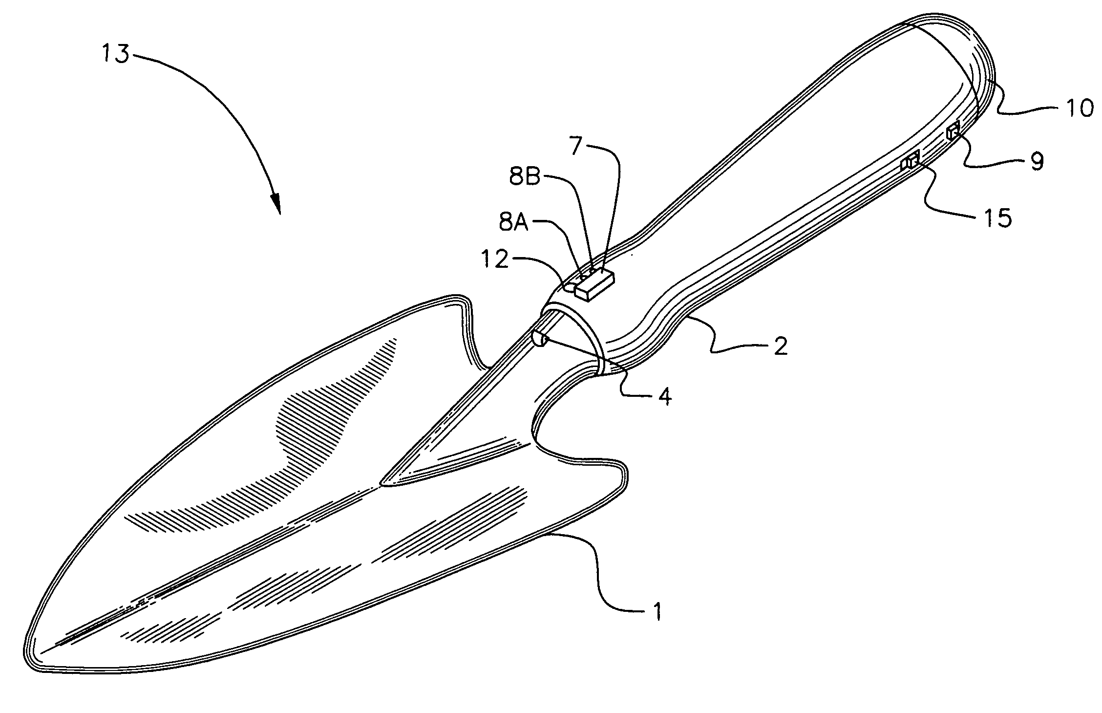
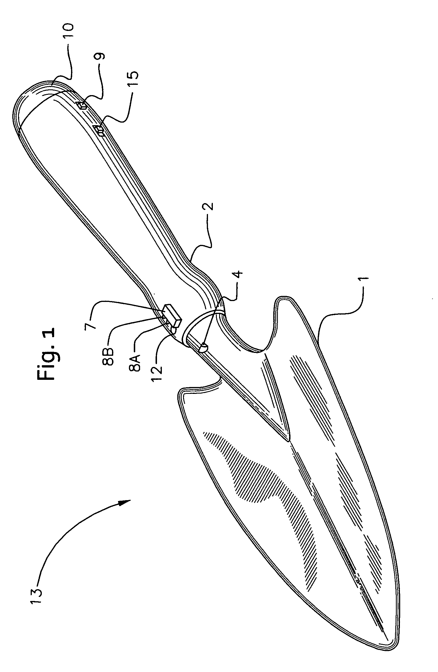
[0059]FIG. 1 discloses a perspective view of a preferred embodiment of a metal detection excavation apparatus 13 according to the present invention. Excavation tool 1 and handle 2 are made of a material which is non-detectable by a metal detector. In a preferred embodiment, excavation tool 1 and handle 2 share a unitary structure and may be formed of a composite plastic material but not limited to. Excavation t...


PUM


Abstract

An excavation apparatus for locating and separating an object from a medium comprising a handle, an excavation tool, a metal detector circuit, at least one coil connected to the metal detector circuit, and at least one output signal device connected to the metal detector circuit. The handle and the excavation tool share a unitary structure. The metal detector circuit is disposed within the handle, and has the at least one coil disposed inside of the excavation tool configured to produce a search field around the excavation tool from within the excavation tool, and the metal detector circuit is configured to notify user with the at least one output signal device when a metallic object is in proximity of the search field.

Description

BACKGROUND OF THE INVENTION[0001]Metal Detectors came into use in the 1930s. This has been a popular hobby for many persons as well as a professional need for locating objects for scientific research or otherwise. As the methodology of metal detectors has evolved, one may use a hand held pin pointer detector to help to locate an object once it has been located by the use of a large metal detector. Shovels and trowels have also been designed and made for the purpose of digging up large and small objects after finding them with the large detectors. Both the shovel and pin-pointer are used to find desired objects in the ground, or other mediums. The shovel may be used to dig up the medium while the pin pointer may be used to locate the metallic object in the medium.[0002]Different scoops have evolved which may be used for scooping to try to locate metallic objects. Many include the use of sifters for letting, for example, sand, go through a sieve to leave other objects behind.[0003]Whi...

Claims


Application Information

Patent Timeline
Patent Type & Authority Applications(United States)
IPC IPC(8): B07B1/02A01B1/02G01V3/10B25B23/18G08B21/00
CPCG01V3/15B07B1/02
Inventor SIEGEL, JACK ALEXANDER
Owner SIEGEL JACK ALEXANDER
Why Eureka
Try Eureka