Microdroplet-based 3-D volumetric displays utilizing emitted and moving droplet projection screens

Active Publication Date: 2010-12-23
I P FOUNDRY
View PDF5 Cites 92 Cited by
  • Summary
  • Abstract
  • Description
  • Claims
  • Application Information

AI Technical Summary

Problems solved by technology

Note that because of the new technology herein, these definitions do not always fit

Method used


Image

  • Microdroplet-based 3-D volumetric displays utilizing emitted and moving droplet projection screens
  • Microdroplet-based 3-D volumetric displays utilizing emitted and moving droplet projection screens
  • Microdroplet-based 3-D volumetric displays utilizing emitted and moving droplet projection screens

Examples


first embodiment

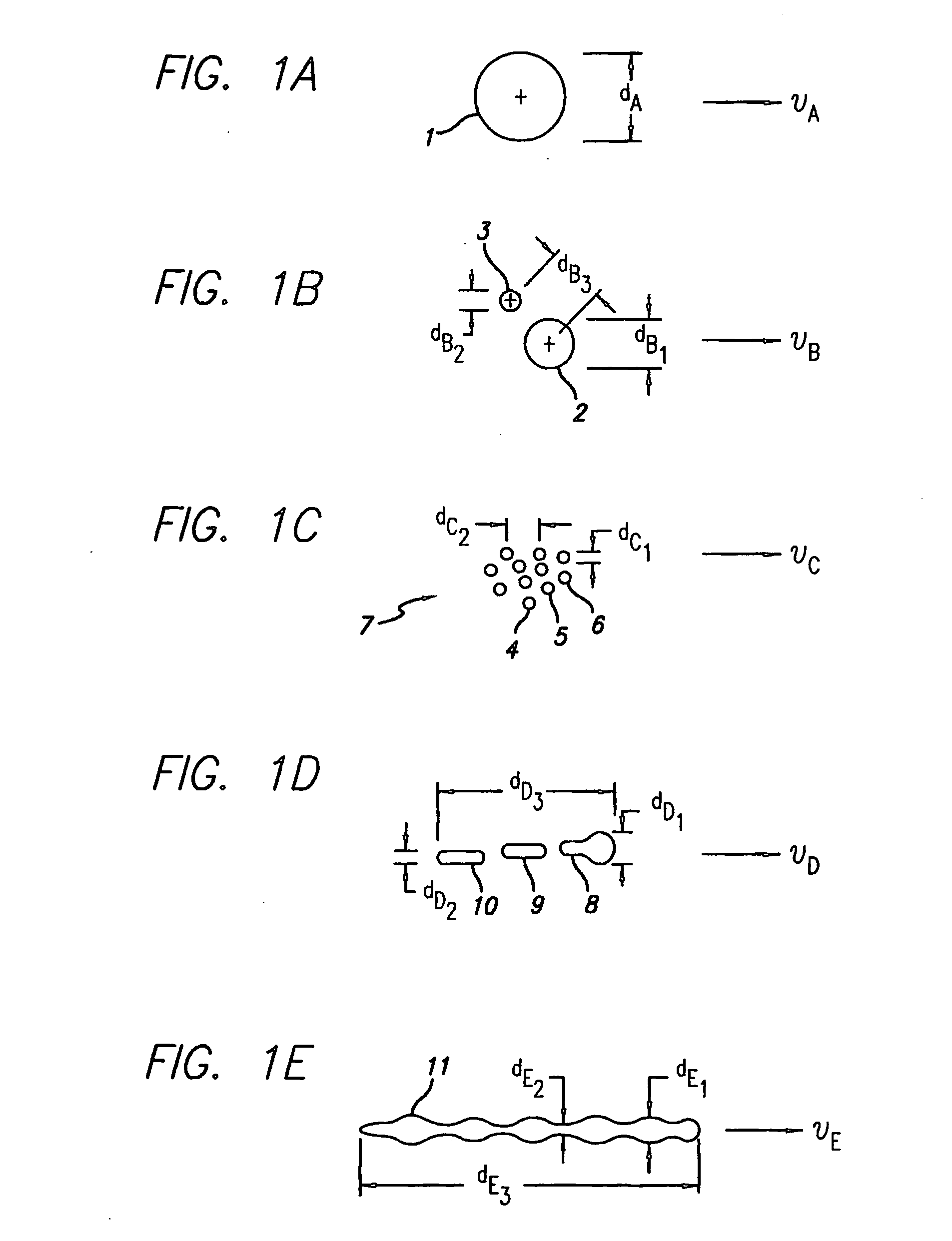
[0132]Moving now to FIG. 1f, we see a film 12 of droplet material that has dimensions of dF2 length by dF3 width by dF1 thickness. The film 12 is moving with a velocity vF. Droplet film 12, in a first embodiment, would have a lateral dimension(s) on the order of one or more voxels and would thereby be utilized to affect the contrast of such one or more voxels. In the case of film 12 being a single voxel droplet film, the voxel is occupied with a tiny plate-like droplet whose thickness dF1 may be considerably less than a voxel dimension. So, for a single voxel application, film droplet 12 might, for example, be 75 microns long, 20 microns wide, and 2 microns thick. A film droplet 12 may be formed by pulsed emission from a slit jet. Alternatively, it could be formed by colliding separate droplets which meet or condense or wet together. Droplet 12 could also have a dimension on the order of several voxels that are all to be activated. We should mention at this point that the droplet fl...

second embodiment

[0237]In the display of FIG. 7a, we remove the (preferably) transparent cylindrical shell 95 such that there is now an open-air gap between the top section 93 and the bottom section 94. One can still maintain a relatively uniform flow across the circular cross-section by doing things such as a) having diameter D be at least as large as height H, and preferably having D being larger than H. A second measure is to maintain a slightly negative pressure for the bottom section 94 relative to the top section 93. This measure minimizes how much of the flow leaks out at an angle to the Y-axis. Also within the scope of the invention is a system having no bottom section 95 (with or without a transparent shell 95) or having a more-substantially separated bottom 94 at a larger H dimension. We stress that as long as the displayable subject matter in the form of entrained droplets such as 100 is relatively close to the top section 93 (or within a remaining shell 95), then the flow in this region,...


PUM


Abstract

Volumetric three-dimensional (3-D) graphical or computer displays are disclosed herein that are capable of presenting objects, data, scenes or other visual information in a realistic or solid-like manner, allowing for an unaided observer to observe such static or moving objects from multiple perspectives with natural depth-cues and superior image quality. We utilize in this refined approach moving-screens formed from particulate-arrays and we preferably optically project multiple image sub-slices on each such flying-screen as it passes through the image-volume thereby minimizing particulate mass-flow since only once screen per image-volume is needed to present the several or many necessary slices of each volumetric frame.

Description

CROSS-REFERENCE TO RELATED APPLICATION[0001]The present application is a continuation-in-part application of application Ser. No. 11 / 036,149, filed Jan. 13, 2005, which claims priority from provisional application Ser. No. 60 / 536,026, filed Jan. 13, 2004.FIELD OF THE INVENTION[0002]The invention is directed to the field of volumetric three-dimensional (3-D) graphical or computer displays which are capable of presenting objects, data, scenes or other visual information in a realistic or solid-like manner allowing for an unaided observer to observe such static or moving objects from multiple perspectives with natural depth-cues and superior image quality.BACKGROUND OF THE INVENTION1) Volumetric Displays—Why Are They Attractive?[0003]Two-dimensional (2-D) display technologies are pervasive and include all manner of CRTs, LCDs, plasma flat panels, more recently OLEDs, and even projected images such as movie screens or slide-show images. They are utilized in everything from televisions, ...

Claims


Application Information

Patent Timeline
IPC IPC(8): H04N13/04H04N13/393
CPCG02B27/2271H04N13/0493G03B25/00G03B21/562G03B21/608H04N13/393G02B30/50G09G3/34
Inventor SLIWA, JOHN W.TOSAYA, CAROL A.
Owner I P FOUNDRY
Why Eureka
Try Eureka