Device for expanding an exit pupil in two dimensions

Active Publication Date: 2010-12-23
MAGIC LEAP
View PDF8 Cites 298 Cited by
  • Summary
  • Abstract
  • Description
  • Claims
  • Application Information

AI Technical Summary

Benefits of technology

[0017]In an embodiment, light is diffracted up to four times to diffraction orders other than zero by the gratings in order to expand a light beam, i.e. once by the input grating, twice by the crossed grating, and once by the output grating. Thus, the image quality may be better than in those prior art approaches which req

Problems solved by technology

However, the small size of a portable device also sets a limitation to the size of a display incorporated in said device.
A typical drawback of a conven

Method used


Image

  • Device for expanding an exit pupil in two dimensions
  • Device for expanding an exit pupil in two dimensions
  • Device for expanding an exit pupil in two dimensions

Examples


Embodiment Construction

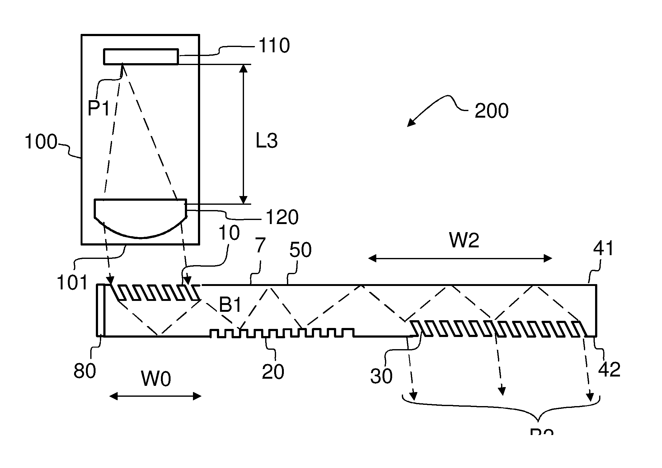
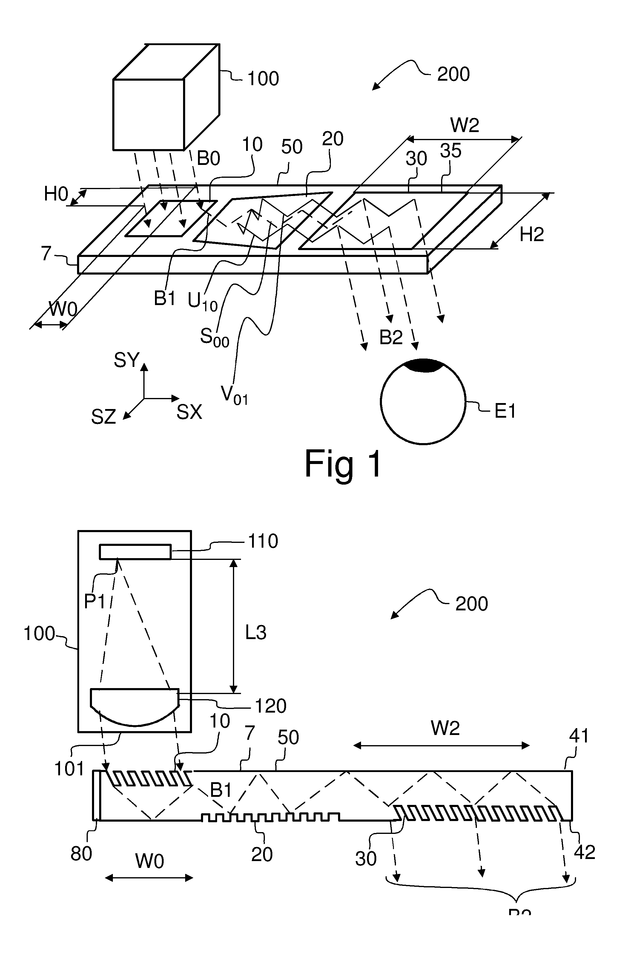
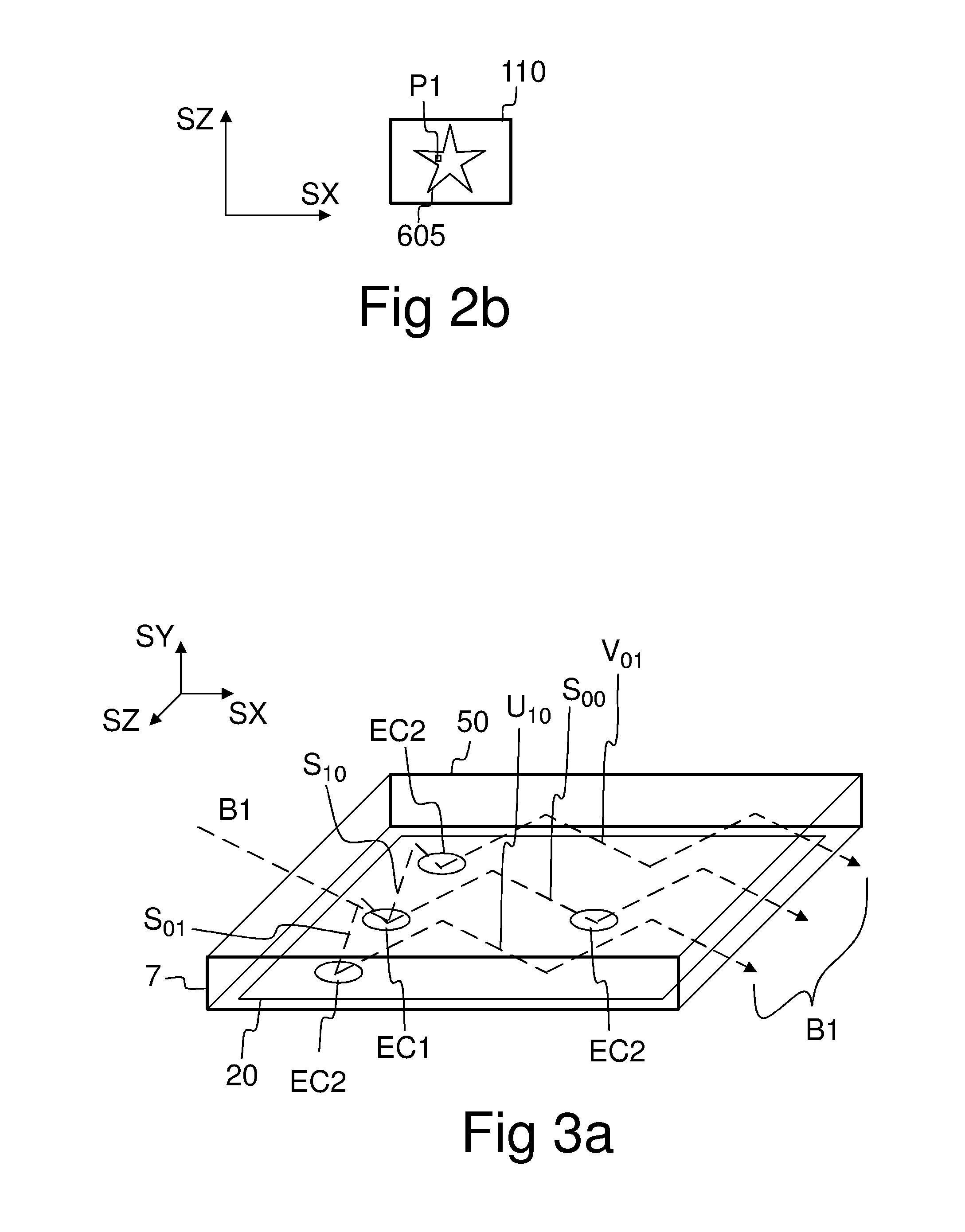
[0041]Referring to FIG. 1, a virtual display device 200 may comprise an optical engine 100 and a diffractive beam expander 50. The optical engine 100 comprises a micro-display 110 and imaging optics 120 (FIG. 2a). The imaging optics 120 converts a real image 605 (FIG. 2b) formed by the micro-display into a virtual image 710 (FIG. 10) which is observable through a viewing aperture 35 of the diffractive beam expander 50.

[0042]The diffractive beam expander 50 comprises an input grating 10, a crossed grating 20, and an output grating 30 implemented on a substantially planar transparent substrate 7. The substrate 7 has a first substantially planar surface, and a second substantially planar surface which is substantially parallel to said first planar surface.

[0043]The substrate 7 is waveguiding, which means that in-coupled light may propagate within said substrate 7 such that said propagating light may be confined to said substrate 7 by total internal reflections (TIR).

[0044]The optical e...


PUM


Abstract

A diffractive beam expander (50) comprises an input grating (10), a crossed grating (20), and an output grating (30) implemented on a planar transparent substrate (7). The crossed grating (20) comprises a plurality of diffractive features (23) arranged along the lines of a first set of parallel lines (25) and along the lines of a second set of parallel lines (26) such that the lines (25) of the first set are parallel to the lines (26) of the second set. The lines of the first set have a first grating period and the lines of the second set have a second grating period. A light beam (B1) coupled into the substrate (7) by the input grating (10) impinges on the crossed grating (20) at a first location (EC1) and further locations (EC2). Interaction at the first location (EC1) provides several sub-beams (S00, S01, S10) which propagate in different directions. Further interactions at second locations (EC2) provide further sub-beams (V01, U10) which propagate in the same direction as the original in-coupled light (B1). Light is subsequently coupled out of the substrate (7) by the output grating (30) to provide a light beam (B2) which is expanded in two directions (SX, SZ) with respect to the beam (B0) impinging on the input grating. A virtual display device (200) may comprise said diffractive beam expander (50).

Description

[0001]The present invention relates to expanding light beams by diffractive elements. The present invention relates also to displaying virtual images.BACKGROUND OF THE INVENTION[0002]Display modules are used in portable devices to display information in graphical form. Small size is an important aspect in portable devices.[0003]However, the small size of a portable device also sets a limitation to the size of a display incorporated in said device. A typical drawback of a conventional small display is that an observer can examine only a small portion of a large displayed image at a glance, while preserving adequate resolution.[0004]Large images may be displayed by a small device e.g. when the device comprises a near-eye virtual display. An imaging optics may convert a small real image generated by a micro-display into a virtual image. An observer may place the device near his eye such that when light provided by the imaging optics impinges on his eye, he perceives an impression of a ...

Claims


Application Information

Patent Timeline
IPC IPC(8): G02B27/44G02B6/34
CPCG02B27/0081G02B27/0172G02B2027/0178G02B27/4272G02B2027/0123G02B27/4205
Inventor LEVOLA, TAPANISAARIKKO, PASI
Owner MAGIC LEAP
Why Eureka
Try Eureka