Illuminating device and packaging method thereof

a technology of illuminating device and packaging method, which is applied in the direction of lighting and heating apparatus, packaging goods type, lighting support device, etc., can solve the problems of increasing complexity and efficiency of manufacture, production cost, and production cost, and achieve the effect of improving the light emitting efficiency of the illuminating devi

Active Publication Date: 2010-12-23
DELTA ELECTRONICS INC
View PDF14 Cites 25 Cited by
  • Summary
  • Abstract
  • Description
  • Claims
  • Application Information

AI Technical Summary

Benefits of technology

[0007]In view of the foregoing, the present invention provides an illuminating device, which can be fabricated though a simplified packaging process with accurate alignment, and a packaging method thereof.
[0011]The first or second barricade is preferably spherical, ellipsoid-shaped, annular, arc-shaped, cone-shaped, cubic, polyhedron-shaped or irregularity-shaped. The first or second barricade is flexible or inflexible, and the material of the first or second barricade includes silica gel, silicone, rubber, resin, glass, acryl, UV gel, light-permeable material, light-proof material or insulation material. Preferably, the first or second barricade is disposed on the substrate by dispensing, adhering, press molding or screen printing. Each of the first and second barricades individually has a first end close to the illuminating element and a second end opposite to the first end and away from the illuminating element, and the first and / or second end is coated with a light-refraction-index converting material in order to improving the light emitting efficiency of the illuminating device.
[0012]The cover layer can be disposed only in the first accommodating area or in the first and second accommodating areas simultaneously. The surface of the cover layer is a concave, convex, flat, mirror or rough surface. The material of the cover layer is light permeable. Moreover, the cover layer includes an optical lens layer, a gel layer or a composite material layer. The optical lens layer can be disposed on the gel layer, the composite material layer, the first barricade or the second barricade. Thus, the barricade can support and fix the optical lens layer. Otherwise, the composite material layer can be disposed on the gel layer or the illuminating element. The material of the optical lens layer can include glass, acryl, UV gel, quartz or highly light-permeable material. In addition, the composite material layer can include a filling gel and a composite material; furthermore, the composite material preferably includes a fluorescent material, a wavelength converting material or a non-crystal material. The composite material is dispersed in the filling gel uniformly, non-uniformly, with a gradually changing concentration, at the bottom, or at the top. As to the material of the filling gel, it includes epoxy, silicone, resin or insulation material.

Problems solved by technology

Unfortunately, in order to accurately aligning the illuminating element 12 in the center of the package layer 14, an additional mechanical apparatus is needed, which may increase the complexity and efficiency of manufacture as well as the production cost.

Method used


Image

  • Illuminating device and packaging method thereof
  • Illuminating device and packaging method thereof
  • Illuminating device and packaging method thereof

Examples


Embodiment Construction

[0018]The present invention will be apparent from the following detailed description, which proceeds with reference to the accompanying drawings, wherein the same references relate to the same elements.

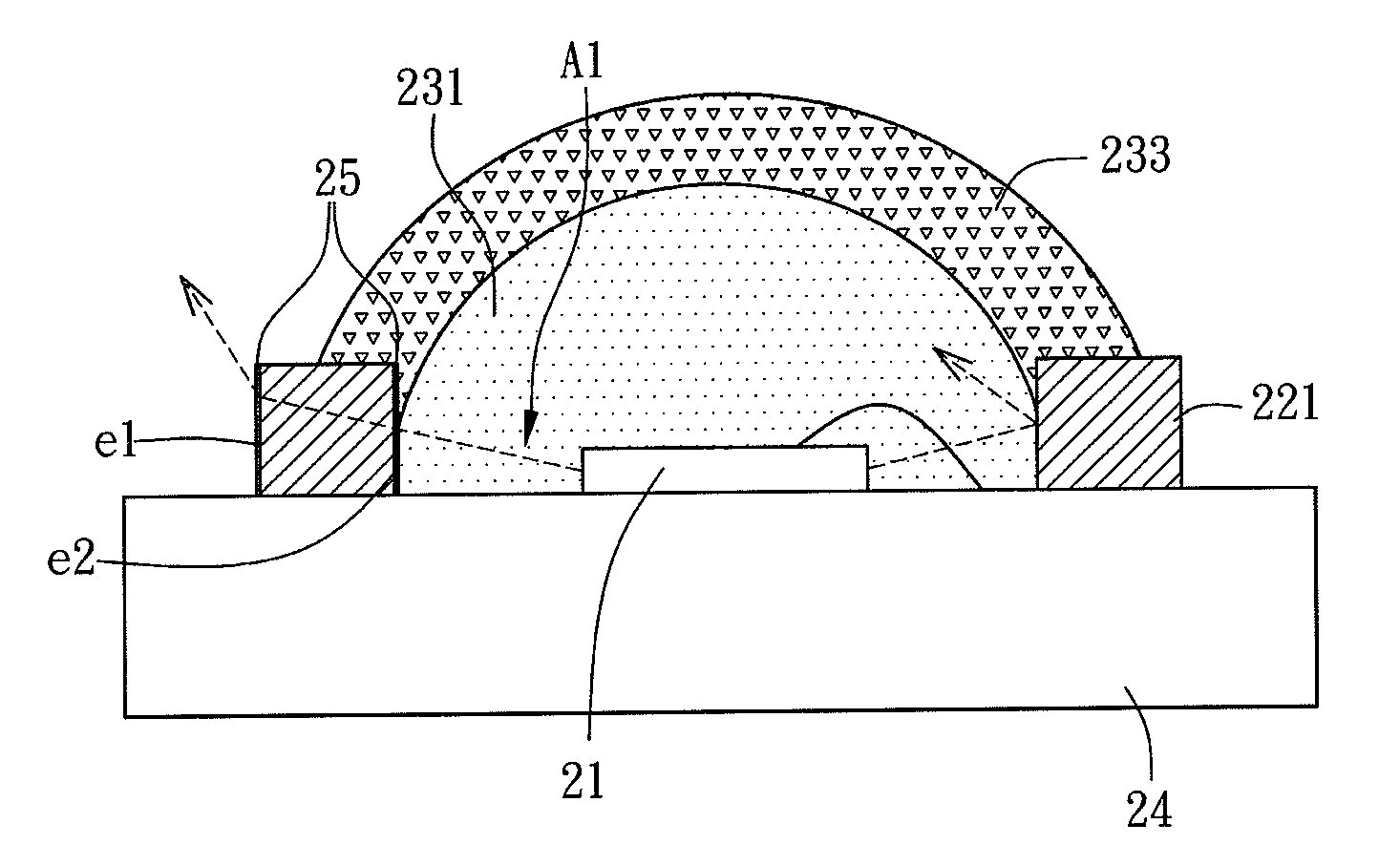
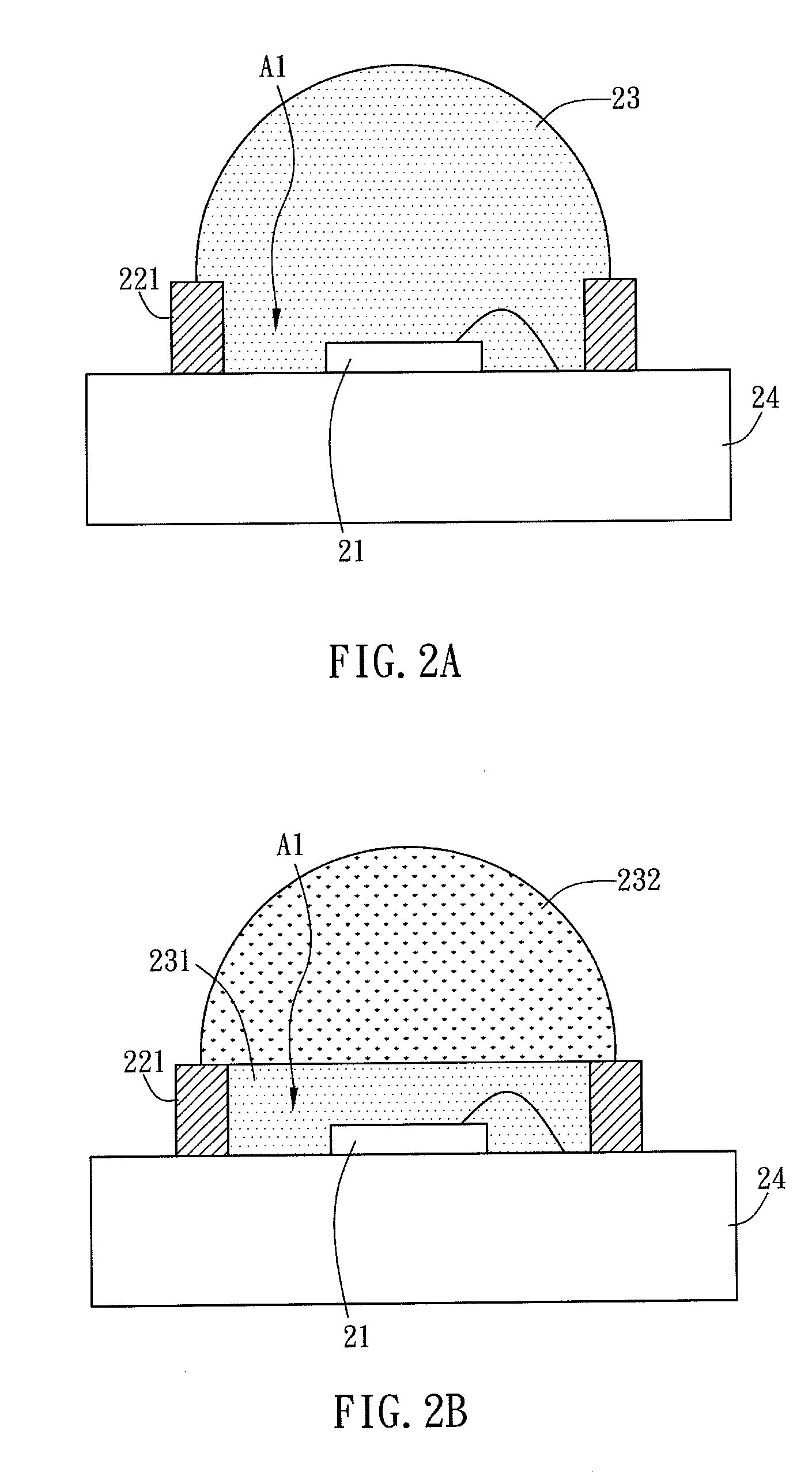
[0019]As shown in FIG. 2A, the illuminating device in accordance with the present invention includes a substrate 24, an illuminating element 21, at least one first barricade 221 and at least one cover layer 23. The first barricade 221 is protruded from a surface of the substrate 24, and is disposed around the illuminating element 21 to define a first accommodating area A1. The cover layer 23 is disposed in the first accommodating area A1 for covering the illuminating element 21.

[0020]Furthermore, the material of the substrate 24 is copper, aluminum, ceramics or high thermal conductivity material, which has the feature of thermal conductivity and circuitry connection. The surface of the substrate can be a flat, convex or concave surface, and preferably the surface of the substrate incl...


PUM

PropertyMeasurementUnit
areaaaaaaaaaaa
accommodating areaaaaaaaaaaa
distancesaaaaaaaaaa

Abstract

An illuminating device includes a substrate, an illuminating element, at least one barricade and at least one cover layer. The illuminating element is disposed on the substrate. The barricade is protruded from a surface of the substrate and disposed around the illuminating element continuously or discontinuously to form a first accommodating area. The cover layer is disposed in the first accommodating area for covering the illuminating element.

Description

CROSS REFERENCE TO RELATED APPLICATIONS[0001]This Non-provisional application claims priority under 35 U.S.C. §119(a) on Patent Application No(s). 098120926 filed in Taiwan, Republic of China on Jun. 23, 2009, the entire contents of which are hereby incorporated by reference.BACKGROUND OF THE INVENTION[0002]1. Field of Invention[0003]The present invention relates to an illuminating device and its packaging method. More particularly, the present invention relates to an illuminating device and a packaging method thereof, which can simplify the packaging process and provide accurate alignment.[0004]2. Related Art[0005]As shown in FIG. 1, the conventional illuminating device 1 has a substrate 10, an insulation layer 11 disposed on the substrate 10, and an illuminating element 12 disposed on the insulation layer 11. Afterward, the illuminating element 12 is connected with a metal layer 13, which is disposed on the insulation layer 11, by wire bonding to establish electrical connection. T...

Claims


Application Information

Patent Timeline
Patent Type & Authority Applications(United States)
IPC IPC(8): F21V9/16F21V21/00F21V7/00F21V3/02B65B5/00
CPCH01L33/54H01L33/56H01L33/60H01L2933/005H01L2224/48091H01L2924/00014H01L2924/181H01L2924/00012
Inventor WU, HSIANG-CHENSHIUE, CHING-CHUANCHEN, CHUN-LANGCHENG, CHUN-HUANG
Owner DELTA ELECTRONICS INC
Why Eureka
Try Eureka