Power Delivery System For HID, LED, Or Fluorescent Track Lighting

a technology for delivering systems and track lighting, which is applied in the direction of lighting and heating apparatus, lighting support devices, and coupling device connections, etc. it can solve the problems of real cost and performance constraints, occupying a relatively large amount of space for power supplies and the enclosures that typically contain them, and not being aesthetically pleasing. , to achieve the effect of extending the average life of lamps and components, and reducing operating and maintenance costs

Active Publication Date: 2010-12-23
LITELAB
View PDF33 Cites 40 Cited by
  • Summary
  • Abstract
  • Description
  • Claims
  • Application Information

AI Technical Summary

Benefits of technology

[0012]Because the power supply is in close contact with the track system, a large amount of the heat energy produced by the power supply is absorbed and diffused by the relatively large thermal mass and surface area that the track or busway provide. This has a measurable beneficial effect on the power supply's electrical and electronic components. It is widely known that operation at elevated temperatures is the main cause of premature failure for electrical and electronic components. Additionally, any lamp in proximity to the power supply may also benefit from this “heat sink” effect that the close contact with the track provides. By operating at relatively lower temperatures the average lifetime of the lamps and components is significantly extended, resulting in more reliable and durable lighting fixtures, and reduced operating and maintenance costs.

Problems solved by technology

Such power supplies and the enclosures that typically contain them may occupy a relatively large amount of space.
This may be problematic in a track lighting system because space is very often in short supply within the track, as many lighting installations call for the use of a large number of fixtures to achieve the required light levels or the desired lighting effects.
There are real cost and performance constraints that require that the power supplies be located in general proximity to the light sources, but not so close that they can be affected by the heat produced by the light sources.
Such an arrangement and the resulting system, however, may not be aesthetically pleasing.

Method used


Image

  • Power Delivery System For HID, LED, Or Fluorescent Track Lighting
  • Power Delivery System For HID, LED, Or Fluorescent Track Lighting
  • Power Delivery System For HID, LED, Or Fluorescent Track Lighting

Examples


Embodiment Construction

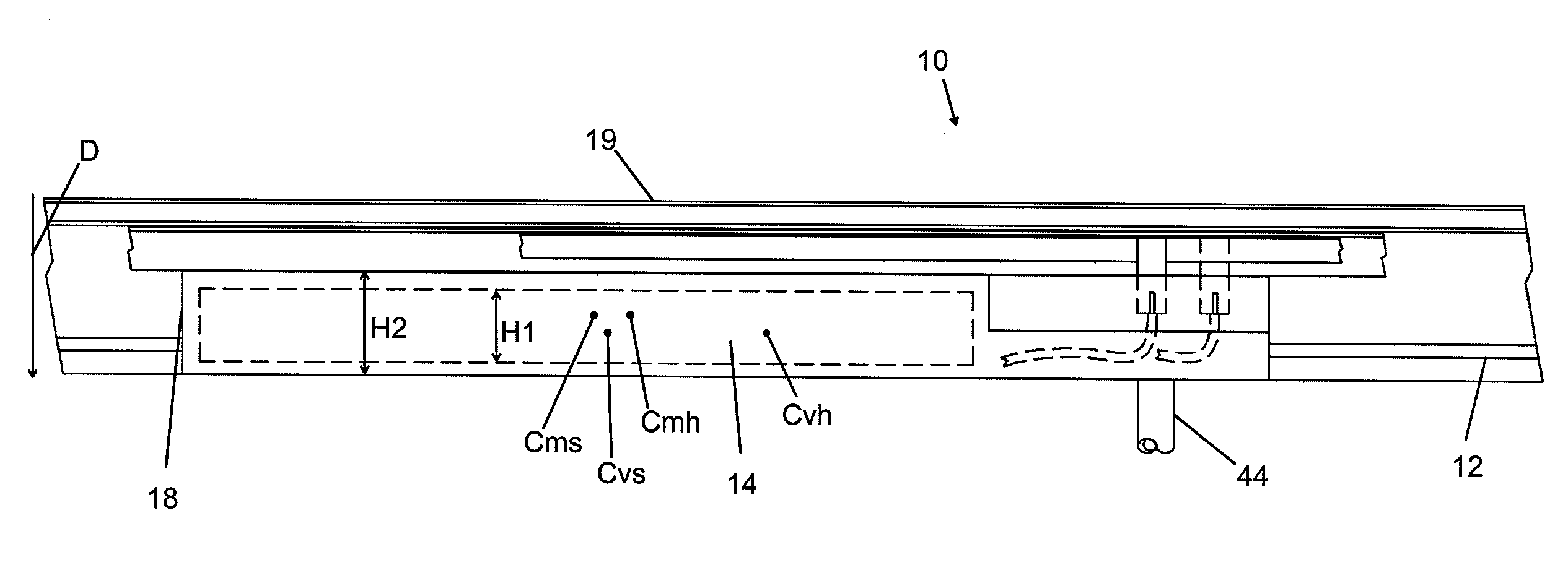
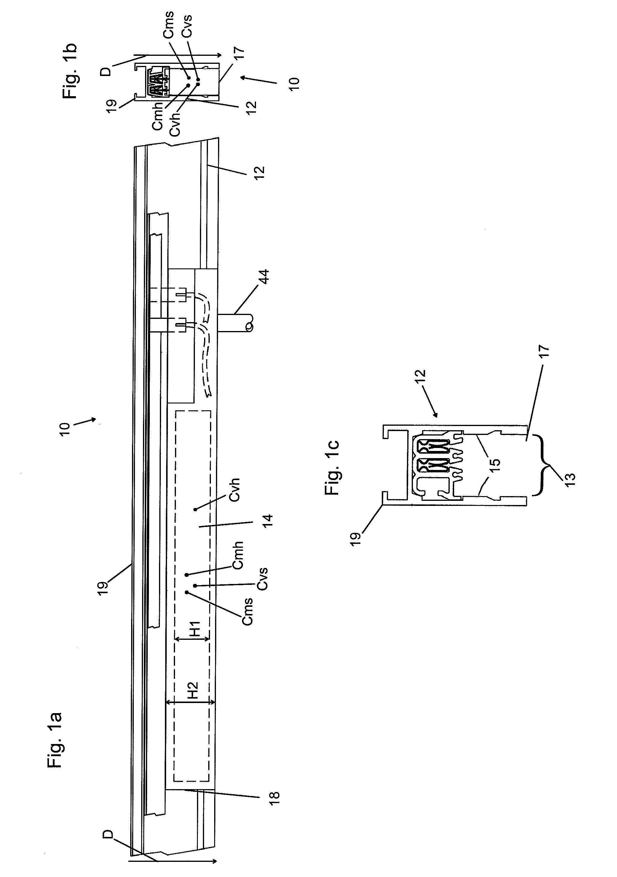
[0045]FIGS. 1a, 1b, and 1c depict a system 10 according to an embodiment of the invention which may include a track 12 having a base 19 and an opening 17. The track 12 may be a busway or a track suitable for lighting systems. Heights of components of the system (designated as H1 and H2) are measured in a direction which is parallel to the base 19-to-opening 17 direction D when the respective components are oriented for insertion into the track 12. The track 12 may be suspended from, recessed into, or mounted on a building structure (for example, a ceiling). A power supply 14 may be substantially contained within the track 12. In this manner, a majority of the power supply 14 may be contained within a channel 13 of the track 12. In one embodiment, less than 50% of the power supply 14 in the direction of height H1 extends beyond the opening 17. In another embodiment, a center of mass Cms of the power supply 14 is within the channel 13 (between sides 15 and within opening 17). In anoth...


PUM


Abstract

A system according to an embodiment of the invention may include a track and a power supply substantially contained within the track. One or more lamps may be electrically connected to the power supply. The lamp may be an HID lamp, an LED lamp, or a fluorescent lamp. The power supply may be a ballast or a transformer, and may comprise a printed circuit board with electrical power handling components on one side. The system may also include a housing which may surround the power supply.

Description

CROSS-REFERENCE TO RELATED APPLICATION[0001]This application claims the benefit of priority to U.S. provisional patent application Ser. No. 61 / 218,308, filed on Jun., 18, 2009, now pending.FIELD OF THE INVENTION[0002]The present invention relates generally to power supplies for track and busway systems, and in particular, to a power supply unit for high-intensity discharge (“HID”), light-emitting diode (“LED”), and fluorescent track light fixtures.BACKGROUND OF THE INVENTION[0003]Track lighting systems are commonplace in many applications, including commercial (e.g. retail store), residential, and museum applications. Track systems offer flexibility such that lighting fixture arrangements may be reconfigured to meet the changing lighting requirements of a space without the need for skilled tradesmen or additional specialized equipment to adjust existing fixtures or to install additional fixtures. Lighting fixtures within track lighting systems may also be readily changed or reconfig...

Claims


Application Information

Patent Timeline
Patent Type & Authority Applications(United States)
IPC IPC(8): F21S8/04H05B37/02F21V23/02
CPCF21V19/0085H01R25/14F21V21/35F21S8/068H05B47/18
Inventor RAMIREZ, RAFAEL M.BESMANOFF, BARRY D.CHRIST, LAWRENCE E.SPAULDING, FREDERICK A.
Owner LITELAB
Why Eureka
Try Eureka