Dolly for track welder-cutter

Active Publication Date: 2010-12-23
CLAUDIO SR ANGEL L
View PDF19 Cites 0 Cited by
  • Summary
  • Abstract
  • Description
  • Claims
  • Application Information

AI Technical Summary

Benefits of technology

[0008]It is, therefore, one of the primary objects of the present invention to provide an apparatus to reduce the risk of back strain for those using track-mounted burning / welding units.
[0010]Still another object of the present invention is to provide an accessory for track burners and welders that readily attaches without tools and makes the burner / welder more mobile.
[0012]An additional object of the present invention is to provide a transporting dolly for track-mounted tools with accessories for enabling free standing.

Problems solved by technology

Carriages, dollies, and other lifting and transporting devices are well known in industry for moving and otherwise facilitating the use of heavy power tools, but not for such track cutting units.

Method used


Image

  • Dolly for track welder-cutter
  • Dolly for track welder-cutter
  • Dolly for track welder-cutter

Examples


Embodiment Construction

, particularly, when such description is taken in conjunction with the attached drawing figures and with the appended claims.

BRIEF DESCRIPTION OF THE DRAWINGS

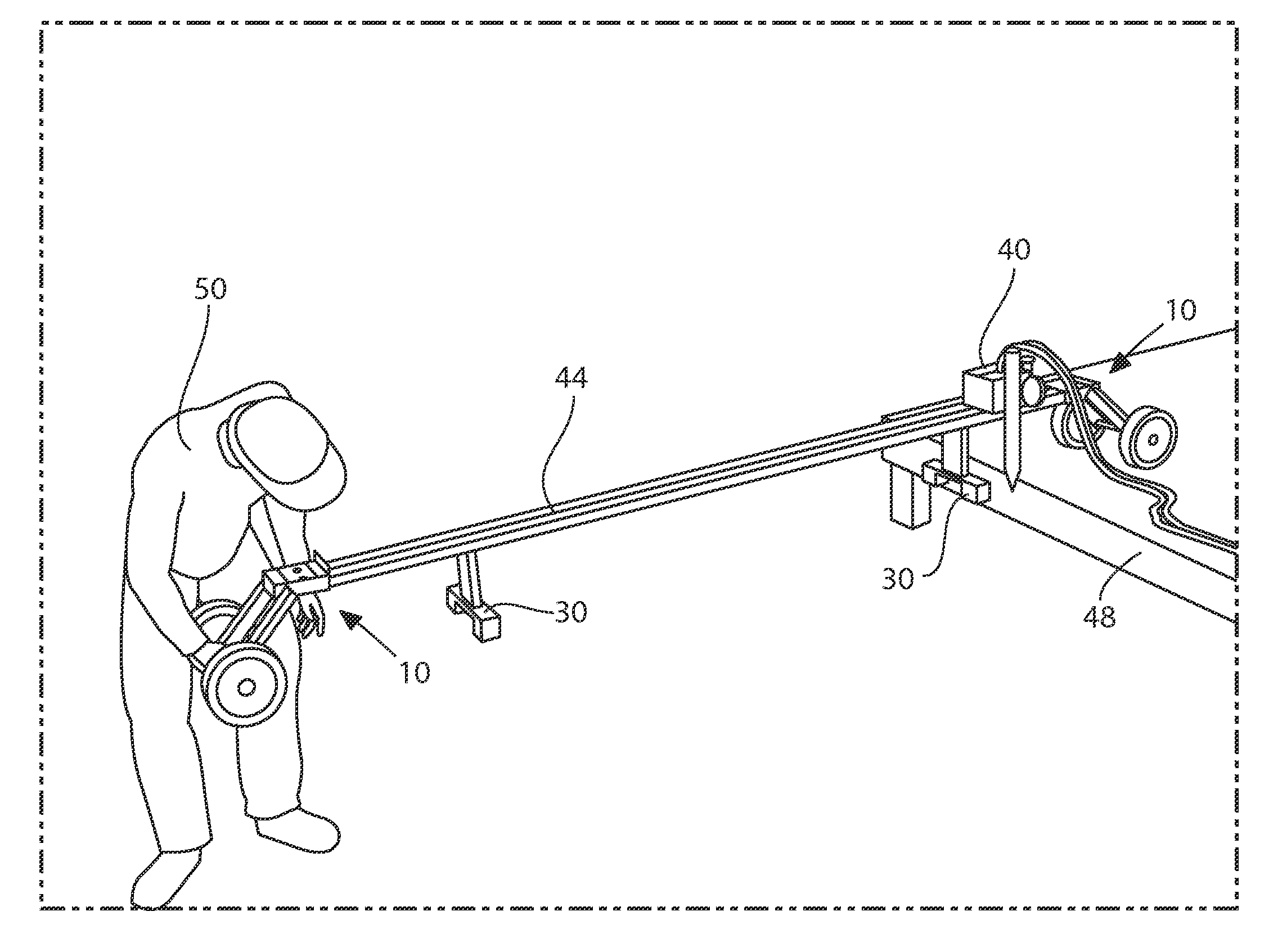
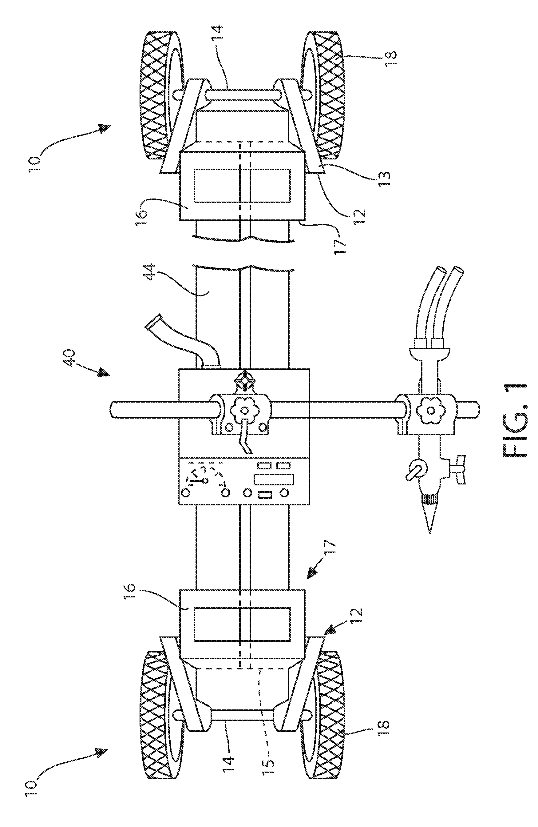
[0014]FIG. 1 is a top plan view of the present invention shown supporting an automated cutting torch.

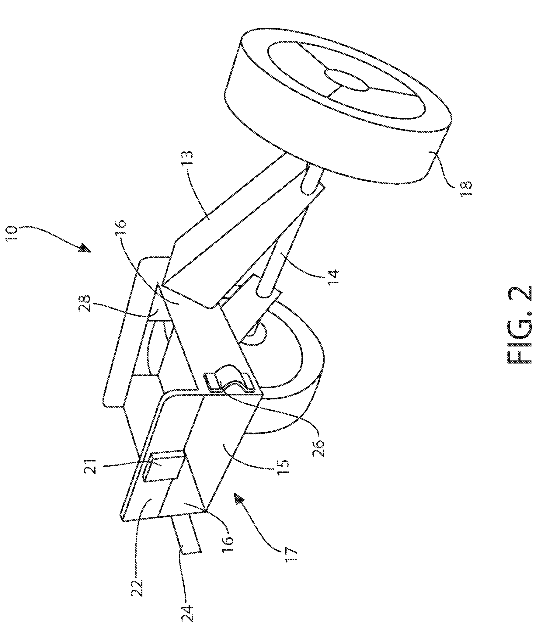
[0015]FIG. 2 is a frontal perspective view of a wheel assembly according to the present invention.

[0016]FIG. 3 is a partial top-side perspective view of one of the two wheel assemblies making up the present invention and illustrating the engagement with one end of a track.

[0017]FIG. 4 is a side perspective view of an alternative embodiment of the present invention.

[0018]FIG. 5 provides a side perspective view of the present invention as it would commonly be used.

[0019]FIG. 6 is a side elevation view of one side of a portion of the wheel assembly of the present invention.

[0020]FIG. 7 is a perspective view of the two wheel assemblies coupled for ready transport.

[0021]FIG. 8 is a perspective view of a wheel assembly with an optiona...


PUM


Abstract

A transporting apparatus for track-mounted machines, also capable of aiding lifting, includes a pair of wheel assemblies. Each wheel assembly consisting of (i) a pair of wheels rotatably attached adjacent ends of an axle; (ii) a pair of parallel spaced-apart axle braces each rotatably engaged to the axle at a distal end of the axle braces; and (iii) a receiver member having a predetermined height and width. This receiver member has at least one bottom member and two spaced-apart substantially parallel side walls fixed to a proximal end of the axle braces.

Description

CROSS REFERENCE TO RELATED APPLICATION[0001]This patent application is related to and claims priority from U.S. Provisional Patent Application Ser. No. 61 / 218,161 filed Jun. 18, 2009.FIELD OF THE INVENTION[0002]The present invention relates, in general, to devices for transporting and operating heavy tools and, more particularly, this invention relates to an apparatus for facilitating the use of traveling welding and / or torch cutting tools.BACKGROUND OF THE INVENTION[0003]Prior to the conception and development of the present invention users of motorized welding-cutting tools, such as the Gullco KAT®, had to manually lift the welding apparatus onto a work table or other elevated areas. Bug-O® offers a similar apparatus. Typically, these motorized burner / welders operate on about an 8-foot long straight rigid track, and the combined apparatus is sometimes called a track burner. Carriages, dollies, and other lifting and transporting devices are well known in industry for moving and oth...

Claims


Application Information

Patent Timeline
IPC IPC(8): B62B5/00B62B3/04B60P3/40
CPCB62B1/008B62B5/0086B62B5/0083
Inventor CLAUDIO, SR., ANGEL L.
Owner CLAUDIO SR ANGEL L
Why Eureka
Try Eureka