Hot Air Stove

Active Publication Date: 2010-12-23
KALUGIN YAKOV
View PDF10 Cites 6 Cited by
  • Summary
  • Abstract
  • Description
  • Claims
  • Application Information

AI Technical Summary

Benefits of technology

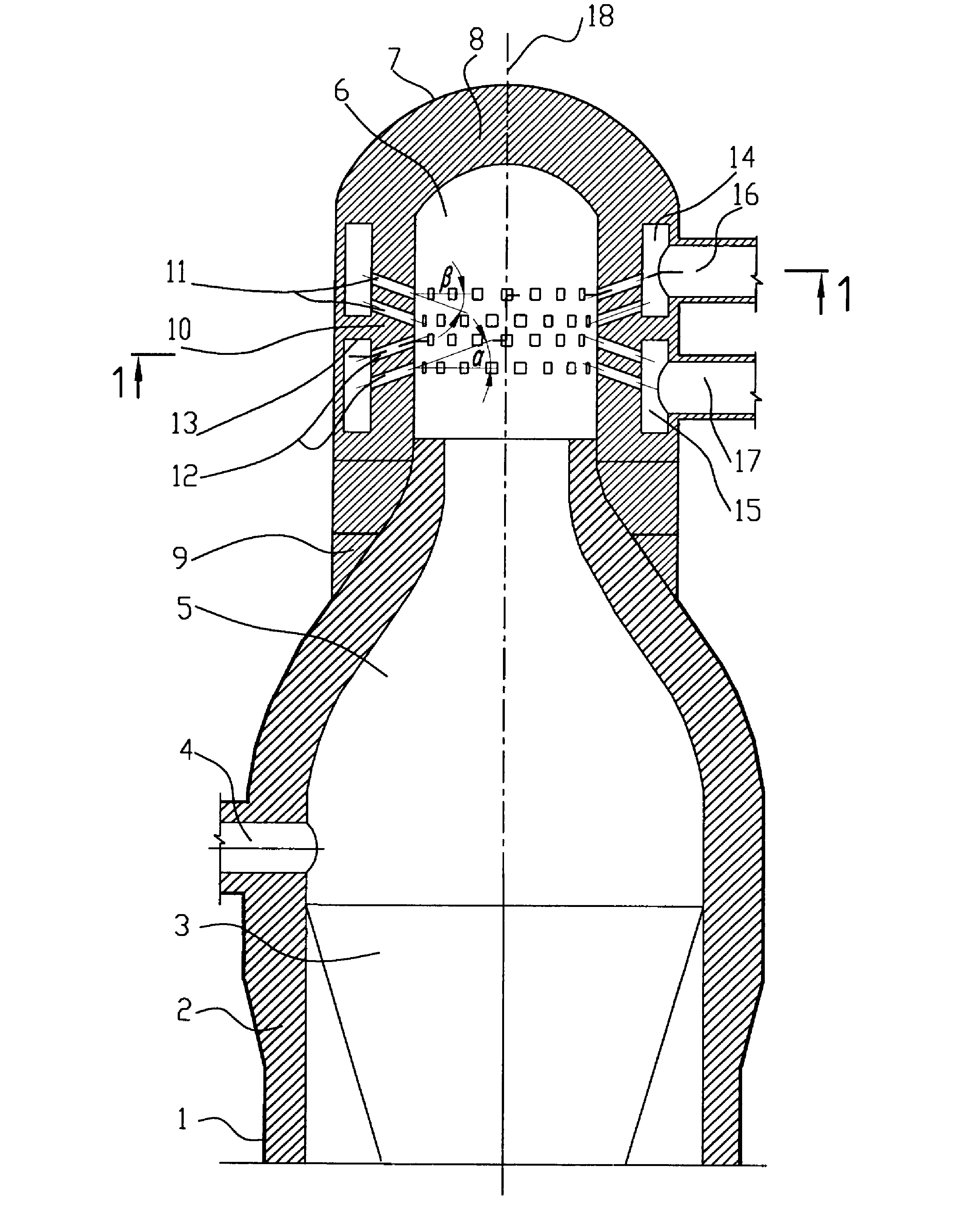
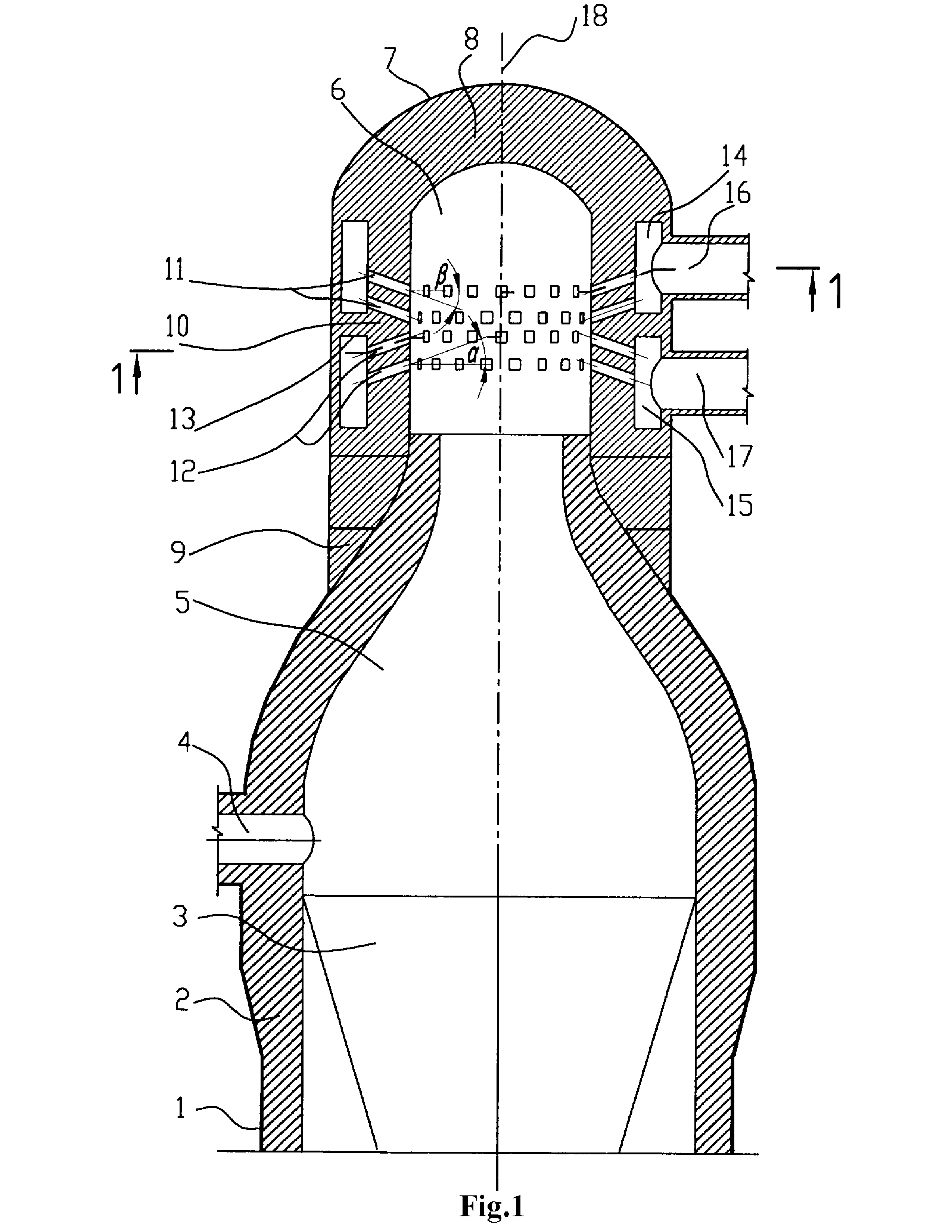
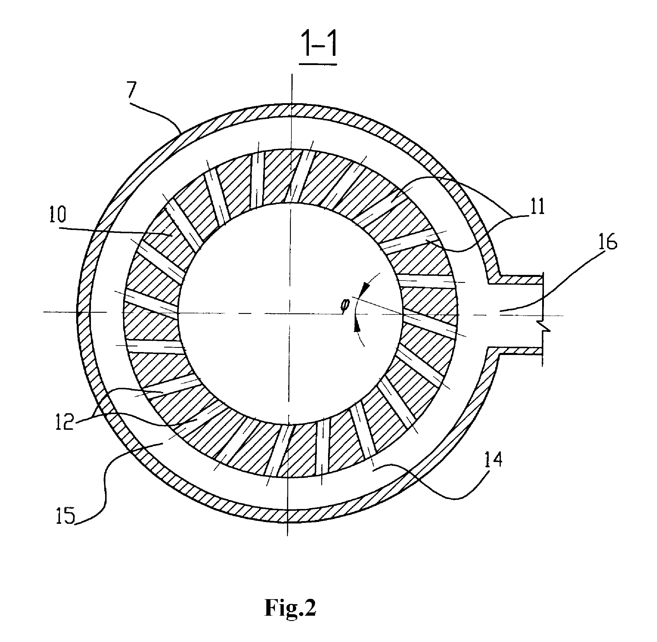
[0010]The execution of the outlet channels in the prechamber, going out of the bottom collector, which are located above and directed upwards at the angle of 15-30 degrees, and outlet channels of the upper collector, located below and directed downwards at the angle of 15-30 degrees, it is possible to direct jets of gas and air towards each other so further they can move in the one way direction vortex of flow, penetrating each other. Flows of air do not need to overcome the jet vortex of gas of the big thickness to get to the center of prechamber since they get there together with jets of gas. High velocities of air jets and air-blowers with high pressure are not required also. The arrangement of projections of axes of all channels on a horizontal p

Problems solved by technology

Blast furnace air heaters are large-sized high-temperature units and require great expenses for their construction and operation.
In addition, air heaters burn great amount of blast furnace gas which structure includes poisoning gas—carbon oxide “CO”.
Besides there can be an incomplete combustion of gas in the central part of prechamber, that will lead to deterioration of ecological parameters of air heaters.
Thus, for chan

Method used


Image

  • Hot Air Stove
  • Hot Air Stove
  • Hot Air Stove

Examples


Example

THE BEST VARIANT OF REALIZATION OF THE INVENTION

[0015]Air heater contains a shell 1 with brick-lining 2, checkerwork 3, hot blast connecting pipe 4, dome 5 with prechamber 6, located at its top, coaxial to it, having shell 7 and brick-lining 8, executed independently of the dome brick lining with an independent support 9 on the shell. The hot blast connecting pipe 4 is located above checkerwork 3 on distance up to its axis not less than 1 diameter of its flow area section. In the vertical wall of the prechamber channels for passing of gas 11 and air 12 are executed, interconnecting with internal collectors 14 and 15, with a separating wall 13 between them and connecting pipes 16 and 17 of gas and air supply. Channels 12 of the bottom collector 15 are located at the top of the collector and directed upwards from horizontal plane at the angle {acute over (α)}=15-30 degrees. Channels 11 of the top collector 14 are located in the bottom of a collector and directed downwards from a horiz...


PUM


Abstract

The inventive air heater comprises a housing (1) with a lining (2), a nozzle (3), a dome (5) with a prechamber (6), which is coaxially positioned in the top part thereof and is provided with a housing (7) and a lining (8) provided with an independent support (9) on the housing (7). Gas (11) and air (12) channels are made in the side vertical wall of the prechamber (10) lining and are connected to internal manifolds (14,15) and to gas (16) and air (17) supplying sleeve fittings. The channels of the lower manifold (15) are arranged in the top part thereof and are upwardly oriented at and angle of 15-30° with respect to a horizontal plane. The channels of the top manifold (14) are arranged in the lower part thereof and are downwardly oriented at an angle of 15-30° to a horizontal plane. The projections of all the channels on a horizontal plane form an angle of 15-45° to the projections of the prechamber radii, passing over the centers of the outlet sections of the channels (11, 12), on a horizontal plane. The use of the invention makes it possible to reduce operation costs and to improve gas burning.

Description

ART[0001]The invention concerns to the area of ferrous metallurgy, in particular to the construction of air heaters for heating up air blast of blast furnaces.FORMER LEVEL OF TECHNIQUE[0002]Air heaters without combustion chamber (shaftless) and with installation of burner devices or prechambers on the dome of the air heater (Patent of Russia No. 2145637, Certificate of Authorship No. 602555, Patent of Japan No. 48-4284, U.S. Pat. No. 3,473,794) are known, which are more perspective.[0003]The closest invention to the proposed one for technical character and combination of features is shaftless air heater according to Patent of Russia No. 2145637, class C21B 9 / 02 (prototype). It has a shell with brick-lining, checkerwork, dome, hot blast connecting pipe, located above the checkerwork on distance up to its axis not less than one diameter of its flow area and also a prechamber, located in the upper part of the dome coaxially with it and having a shell with brick-lining, executed indepen...

Claims


Application Information

Patent Timeline
IPC IPC(8): C21B9/00
CPCC21B9/02F27D99/0001F27B1/10C21B9/14
Inventor KALUGIN, YAKOV
Owner KALUGIN YAKOV
Why Eureka
Try Eureka