
Electrostatic loudspeaker stators and their manufacture

a loudspeaker and electrostatic technology, applied in the direction of electrostatic transducer loudspeakers, electrical transducers, cores/yokes, etc., can solve the problems of difficult manufacturing, and achieve the effect of reducing the unit cost of manufacture, facilitating high-volume production, and facilitating creation

Inactive Publication Date: 2010-12-30
IMMERSION TECH PROPERTY
View PDF3 Cites 1 Cited by
  • Summary
  • Abstract
  • Description
  • Claims
  • Application Information

AI Technical Summary

Benefits of technology

[0020]The above described methods have several advantages, including ease of creation of complex shapes which can have advantages in terms of sound reproduction, ease of high volume production, lower unit cost of manufacture compared to traditional methods, high degree of accurate repeatability irrespective of the quantity of stators produced, high dimensional accuracy allowing consistency of sound reproduction between speakers. Additional advantages include the ability to manufacture composite structures using two or more different materials and the maintenance of close dimensional tolerances inherent in moulding processes allows reduction of stator to diaphragm air gaps, resulting in improved efficiency of sound reproduction. Also a wide range of possible shapes can be created to improve aesthetics and nodes can be incorporated in the design, eliminating the need for manual insertion. With some stator designs, a complete stator can be created in one manufacturing operation. The stators can be fully self supporting, that is, there is no need for an external support structure, and they can be formed with a high level of electrical insulation between the electrically conducting stator elements and the external environment without any separate interposing insulation. This provides a high degree of inherent electrical safety, that is, it is safe for human contact.

Problems solved by technology

They can therefore be difficult to manufacture because of the required degree of accuracy.

Method used


Image

  • Electrostatic loudspeaker stators and their manufacture
  • Electrostatic loudspeaker stators and their manufacture
  • Electrostatic loudspeaker stators and their manufacture

Examples


Embodiment Construction

[0032]In the drawings corresponding features or elements in the various figures are indicated by a common reference numeral for ease of understanding.

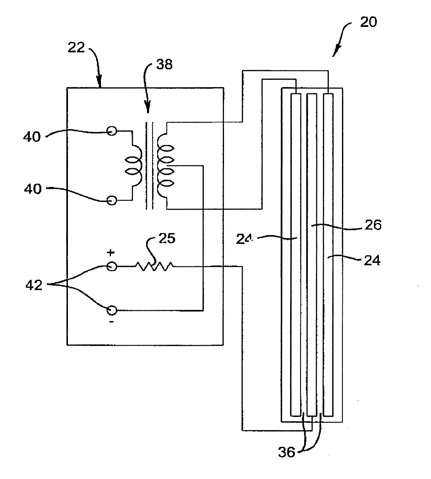
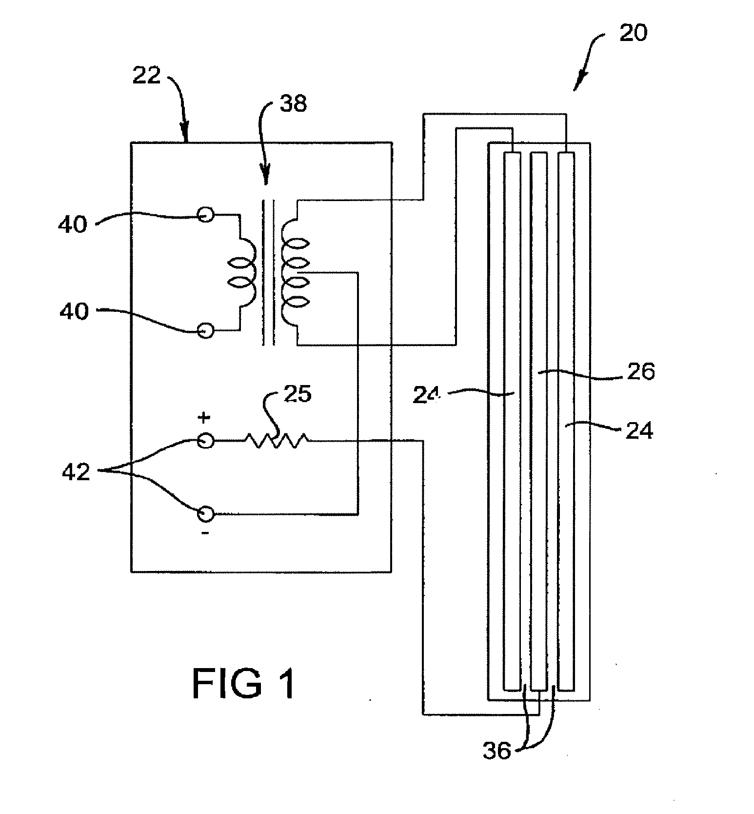
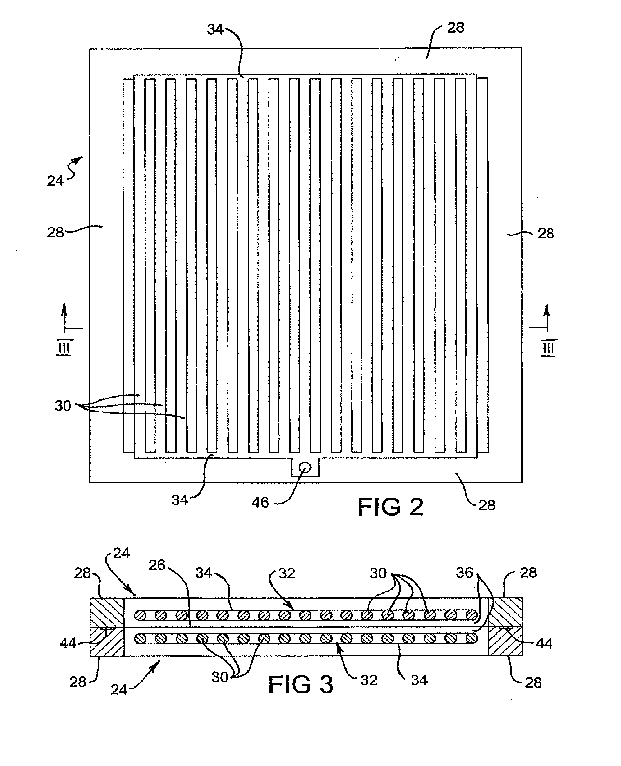
[0033]The schematic electrostatic loudspeaker system of FIG. 1 comprises an electrostatic loudspeaker 20 and circuitry 22 for driving the electrostatic loudspeaker 20. The electrostatic loudspeaker 20 includes spaced apart first and second stators 24 between which is located an electrically conductive diaphragm 26. Each stator 24 comprises an insulating peripheral frame 28 (see FIGS. 2 and 3) which supports a multiplicity of electrically conductive stator elements 30 forming a grid 32, that is a multiplicity of parallel rigid “rods” or “bars”30 which are connected together electrically by at least end connections 34. The stators 24, because of the grid structure 32, are acoustically transparent to audio sound output. The frames 28 of the stators 24 support the diaphragm 26, which is lightly tensioned across and attached to the frame 28...


PUM


Abstract

A method for manufacturing a stator (24) for an electrostatic loudspeaker in which at least a part of a structure (28) for forming the stator (24) is moulded from an electrically insulating material. This structure (28) may be a frame of the stator. To complete the stator (24), electrically conductive portions (30) are combined with the moulded structure to form a complete structure that includes an electrically conductive grid (29). The electrically conductive portions (30) may be a preformed grid (29). The frame (28) and the grid (29) may be pressfitted together. Alternatively the moulded structure may be electrically conductive, and electrically insulating portions may be combined with it to form a complete stator. Manufacture of electrostatic loudspeaker stators using a moulding process allows for relatively low cost production methods that can repeatedly achieve a required high degree of accuracy.

Description

CROSS-REFERENCE TO RELATED APPLICATIONS[0001]This application is a Continuation Application of U.S. application Ser. No. 11 / 997,740 filed Jun. 5, 2008, which is the U.S. National Phase of PCT / AU2006 / 001100 filed Aug. 4, 2006. PCT / AU2006 / 001100 claims priority from Australian Application No. 2006901861 filed Apr. 10, 2006, Australian Application No. 2006900608 filed Feb. 8, 2006 and Australian Application No. 2005904224 filed Aug. 5, 2005. The subject matter of each of the above-referenced applications is incorporated in entirety by reference.TECHNICAL FIELD[0002]The present invention relates to electrostatic loudspeaker stators and their manufacture.BACKGROUND[0003]A reference herein to a patent document or other matter which is given as prior art is not to be taken as an admission that that document or matter was, in Australia, known or that the information that it contains was part of the common general knowledge as at the priority date of any of the claims of the present applicat...

Claims


Application Information

Patent Timeline
Patent Type & Authority Applications(United States)
IPC IPC(8): H04R31/00
CPCH04R19/02H04R31/00Y10T29/49005Y10T29/49009Y10T29/4908Y10T29/49012
Inventor VAN DONGEN, CHARLES CORNELESCHAMPION, LINDSAY ALFREDEVANS, EVAN DOUGLASEVANS, CRAIGHOWARD, GROVER LATHAMMACKINLAY, ROBERT NEIL
Owner IMMERSION TECH PROPERTY
Learn More