Quench chamber assembly for a gasifier

a gasifier and quench chamber technology, applied in the field of quench chamber assembly of gasifiers, can solve the problems of excessive liquid carried from the quench chamber and into downstream equipment, and operational problems

Inactive Publication Date: 2010-12-30
GENERAL ELECTRIC CO
View PDF10 Cites 48 Cited by
  • Summary
  • Abstract
  • Description
  • Claims
  • Application Information

AI Technical Summary

Benefits of technology

[0008]In accordance with another exemplary embodiment of the present invention, a gasifier includes a deflector plate disposed between a liquid coolant and an exit path of a quench chamber. The cooled syngas is directed through the annular passage and i

Problems solved by technology

However, excessive liquid carried from the quench chamber and i

Method used


Image

  • Quench chamber assembly for a gasifier
  • Quench chamber assembly for a gasifier
  • Quench chamber assembly for a gasifier

Examples


Embodiment Construction

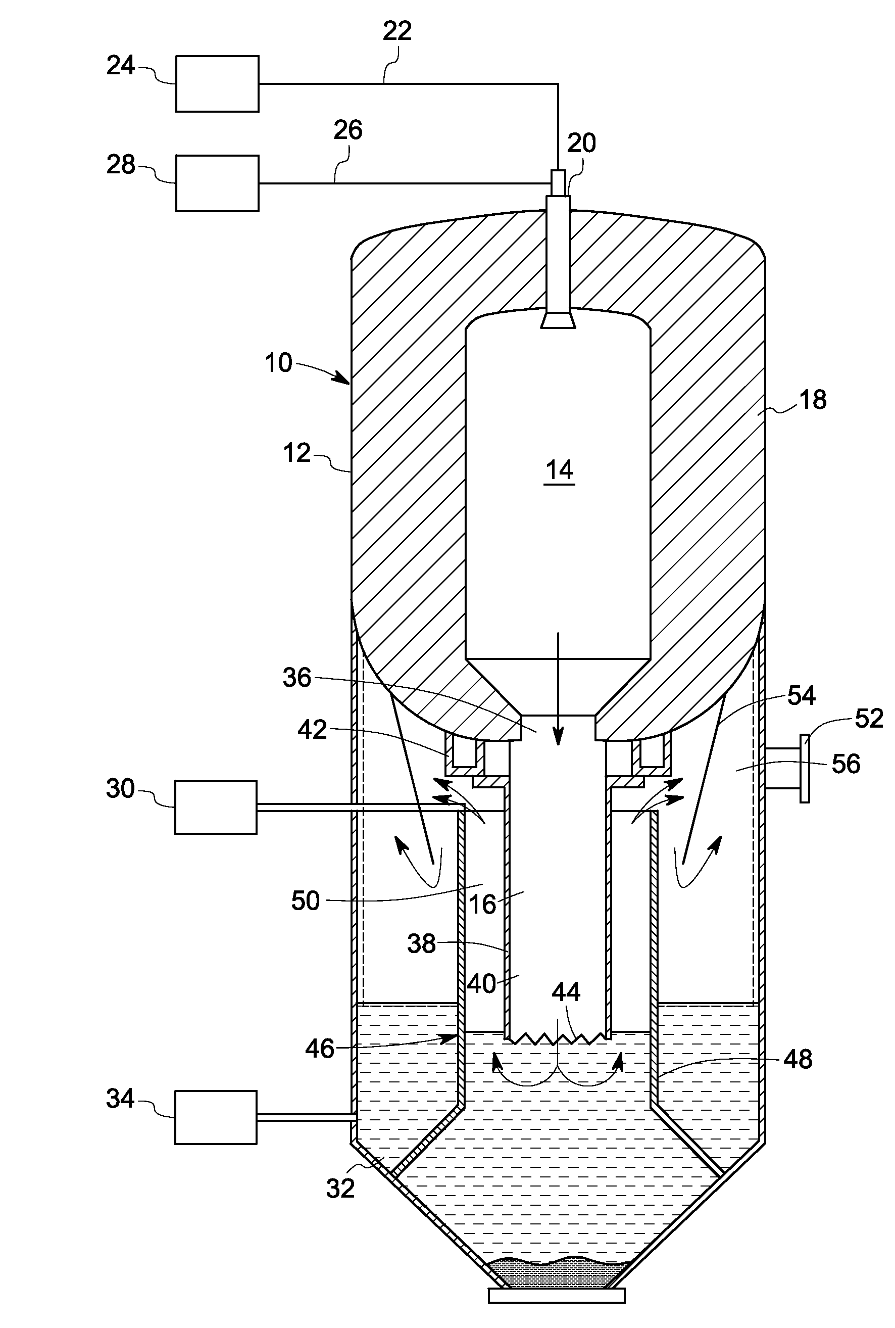
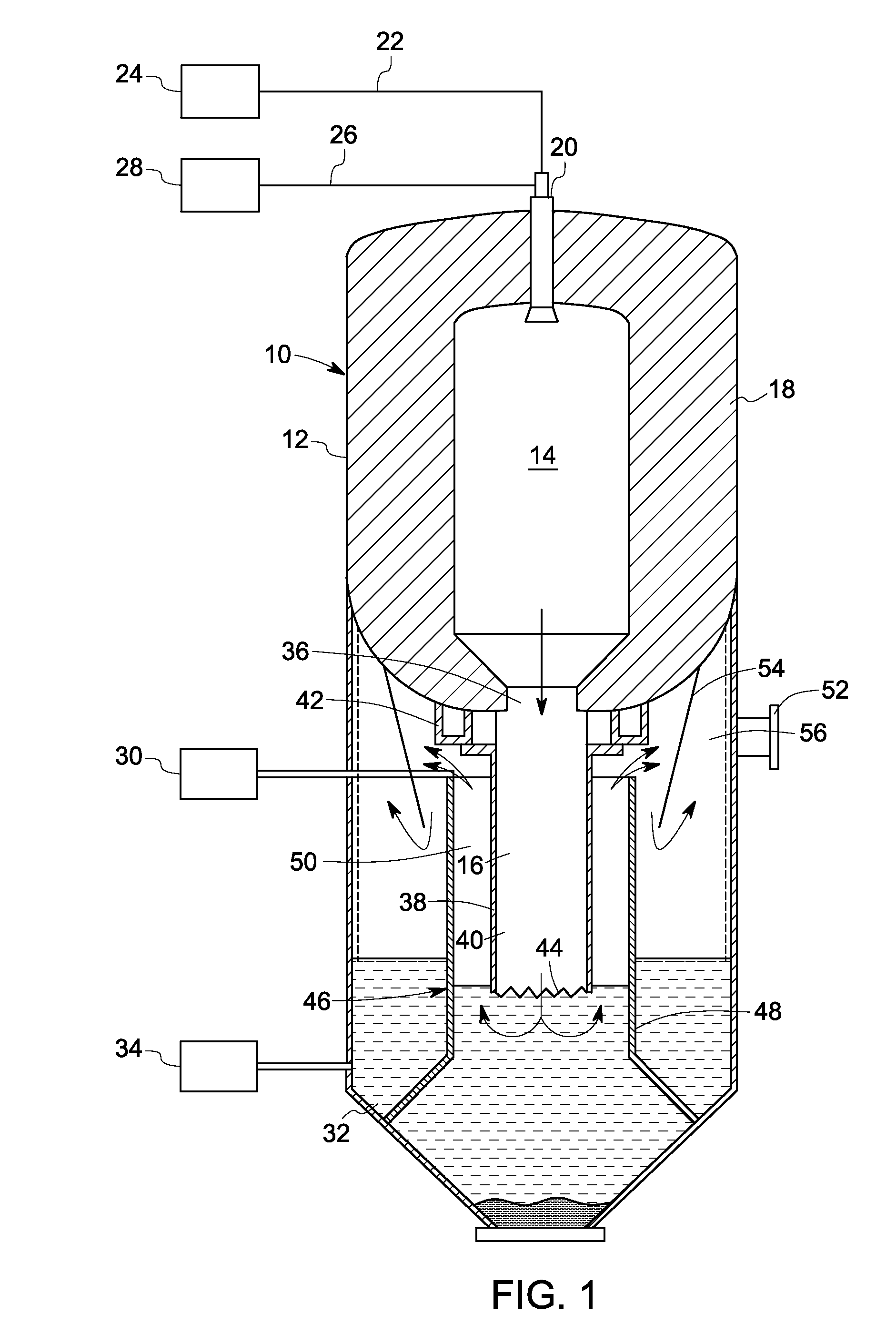
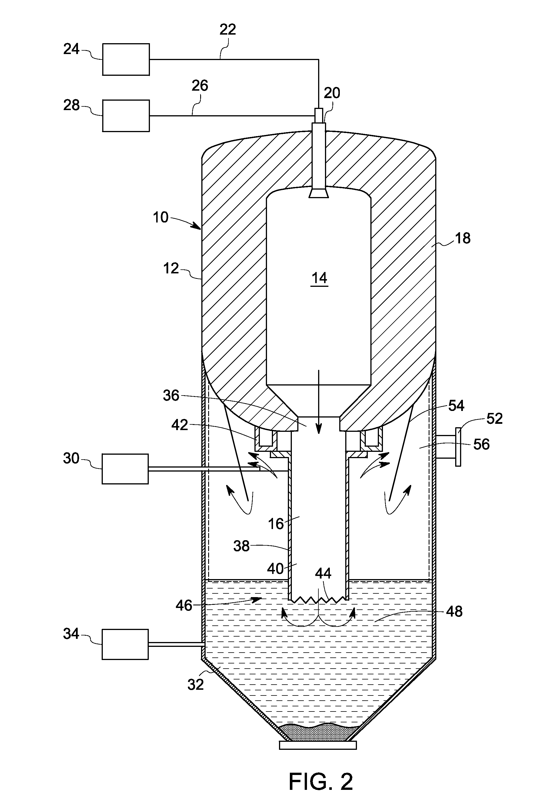
[0038]In accordance with the exemplary embodiments disclosed herein, a gasifier having a quench chamber assembly configured to reduce temperature of syngas downstream of a combustion chamber is disclosed. The gasifier includes a quench chamber containing a liquid coolant disposed downstream of the combustion chamber. A syngas generated from the combustion chamber is directed via a dip tube to the quench chamber to contact the liquid coolant and produce a cooled syngas. A baffle is disposed proximate to an exit path of the quench chamber. The baffle may be a symmetric or asymmetric shaped baffle. A draft tube is disposed surrounding the dip tube such that an annular passage is formed between the draft tube and the dip tube. The cooled syngas is directed through the annular passage and impacted against the baffle so as to remove entrained liquid content from the cooled syngas before the cooled syngas is directed through the exit path. In some embodiments, a deflector plate is disposed...


PUM


Abstract

A gasifier includes a combustion chamber in which a combustible fuel is burned to produce a syngas and a particulated solid residue. A quench chamber having a liquid coolant is disposed downstream of the combustion chamber. A dip tube is disposed coupling the combustion chamber to the quench chamber. The syngas is directed from the combustion chamber to the quench chamber via the dip tube to contact the liquid coolant and produce a cooled syngas. A draft tube is disposed surrounding the dip tube such that an annular passage is formed between the draft tube and the dip tube. An asymmetric or symmetric baffle is disposed proximate to an exit path of the quench chamber. The cooled syngas is directed through the annular passage and impacted against the asymmetric or symmetric baffle so as to remove entrained liquid content from the cooled syngas before the cooled syngas is directed through the exit path.

Description

CROSS-REFERENCE TO RELATED PATENT APPLICATIONS[0001]This application is related to the following co-pending U.S. patent applications having Ser. No. {Attorney Docket No. 239050-1}, entitled “COOLING CHAMBER ASSEMBLY FOR A GASIFIER” and Serial No. {Attorney Docket No. 236150-1}, entitled “GASIFICATION SYSTEM FLOW DAMPING” assigned to the same assignee as this application and filed concurrently herewith, each of which is hereby incorporated by reference.BACKGROUND[0002]The invention relates generally to gasifiers, and more particularly to a quench chamber assembly for a gasifier.[0003]In a normal coal gasification process, wherein a particulated carbonaceous fuel such as coal or coke or a carbonaceous gas is burned, the process is carried out at relatively hot temperatures and high pressures in a combustion chamber. When injected fuel is burned or partially burned in the combustion chamber, an effluent is discharged through a port at a lower end of the combustion chamber to a quench c...

Claims


Application Information

Patent Timeline
IPC IPC(8): C10J3/72
CPCC10J3/84C10J3/845Y02E60/324C10J3/485C10J2200/09C10K1/08Y02E60/32
Inventor TIWARI, PRASHANTLASKOWSKI, GREGORY MICHAELCORRY, JUDETH BRANNONKLOCKOW, HELGE BURGHARD HERWIGJIMENEZ-HUYKE, ALLYSON JOYBHAISORA, SHAILESH SINGHRUSSELL, STEVEN CRAIGHARDCASTLE, KARLMOYER, JENNIFER LYNNPARENT, SCOTT REGINALDMOHSIN, YULIANTO SALAHUDDIN
Owner GENERAL ELECTRIC CO
Why Eureka
Try Eureka