Solar concentrator with induced dipole alignment of pivoted mirrors

a technology of solar concentrator and dipole alignment, which is applied in the field of solar energy concentrator fresnel reflector array, can solve the problem of no prior ar

Inactive Publication Date: 2010-12-30
RABINOWITZ MARIO
View PDF30 Cites 17 Cited by
  • Summary
  • Abstract
  • Description
  • Claims
  • Application Information

AI Technical Summary

Benefits of technology

[0042]If double back-to-back mirrors are used, an option presents itself to use the better surface as the surface that reflects the light, and furthermore to have a standby mirror in each element should one of the mirrors degrade. A permanent electret dipole can be sandwiched between the two induced dipole mirrors to further enhance the dipole field that interacts with the addressable alignment fields.
[0046]In the adjustable Fresnel reflectors solar concentrator with induced dipole alignment of pivoted mirrors that has been developed, the induced dipole aligns the optical elements to concentrate solar energy on a receiver having dimensions small compared to the dimensions of the array. This permits the focal point of the array to remain focused on the receiver over the course of a day and throughout the year.
[0048]There are many aspects and applications of this invention, which provides techniques applicable individually or in combination as an actuator, for motion control, and for positioning of the optical elements of a solar concentrator and similar equipment. The broad general concept of this invention relates to the actuation, motion production and control, and positioning resulting from an induced dipole interaction of pivoted mirrors in electric fields by an electronic control grid. The instant invention can perform dynamic motion control over a wide range of dimensions from nanometers to centimeters, i.e. from the nano-range, through the micro-range, through the mini-range to the macro-range in a broad scope of applications in micro-electro-mechanical systems (MEMS) such as a solar concentrator, and in similar equipment such as optical switching to macro-positioning. Motorless linear motion, angular deflection, and continuous rotation are achieved without recourse to magnetic fields thus eliminating the need for coils. Furthermore, the instant invention permits less costly and greater ease of manufacture while providing well-defined motion and position control.

Problems solved by technology

No prior art was found that utilized induced dipole alignment in electric fields of pivoted mirrors in a Fresnel reflector solar concentrator, optical switches, displays, or other similar equipment.

Method used


Image

  • Solar concentrator with induced dipole alignment of pivoted  mirrors
  • Solar concentrator with induced dipole alignment of pivoted  mirrors
  • Solar concentrator with induced dipole alignment of pivoted  mirrors

Examples


Embodiment Construction

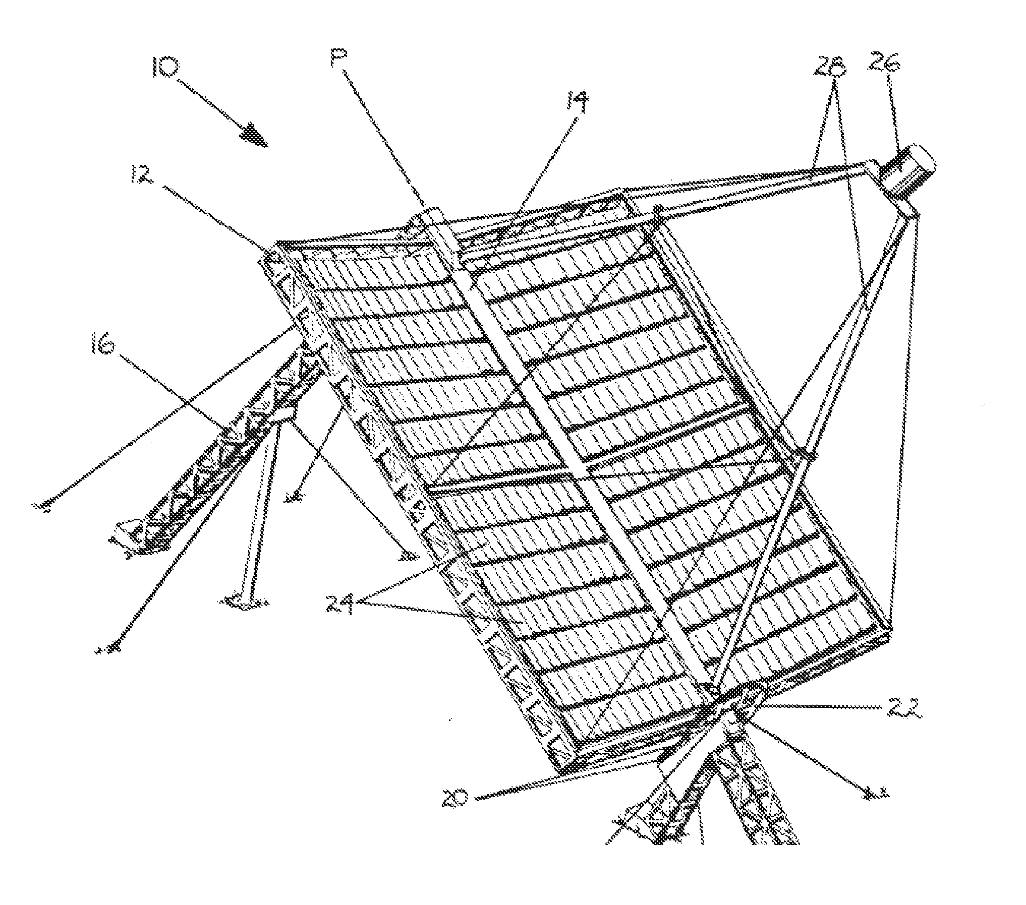
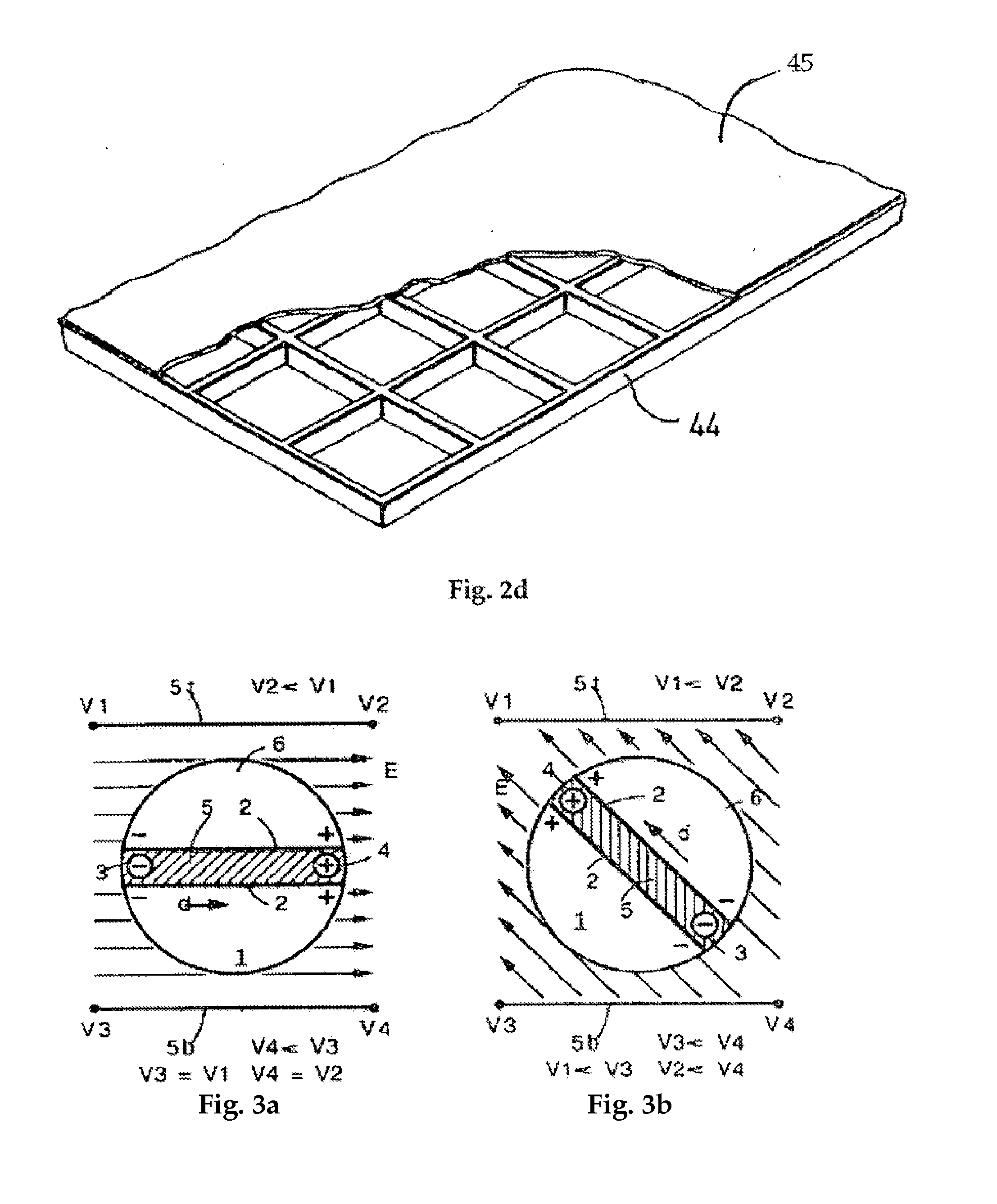
[0105]As is described here in detail, the objectives of the instant invention may be accomplished by any of a number of ways separately or in combination, as taught by the instant invention. A tracking solar concentrator has been developed in which the orientation of individual optical elements (mirrors, reflectors, lenses) is accomplished by electric dipole interaction between the electric field of a grid and an induced dipole, and / or an electret dipole, to align them consecutively or concurrently without the need for expensive, bulky, and heavy motors. Thus the improved solar concentrator of the instant invention can be less expensive, more reliable, and lighter in weight than conventional solar arrays.

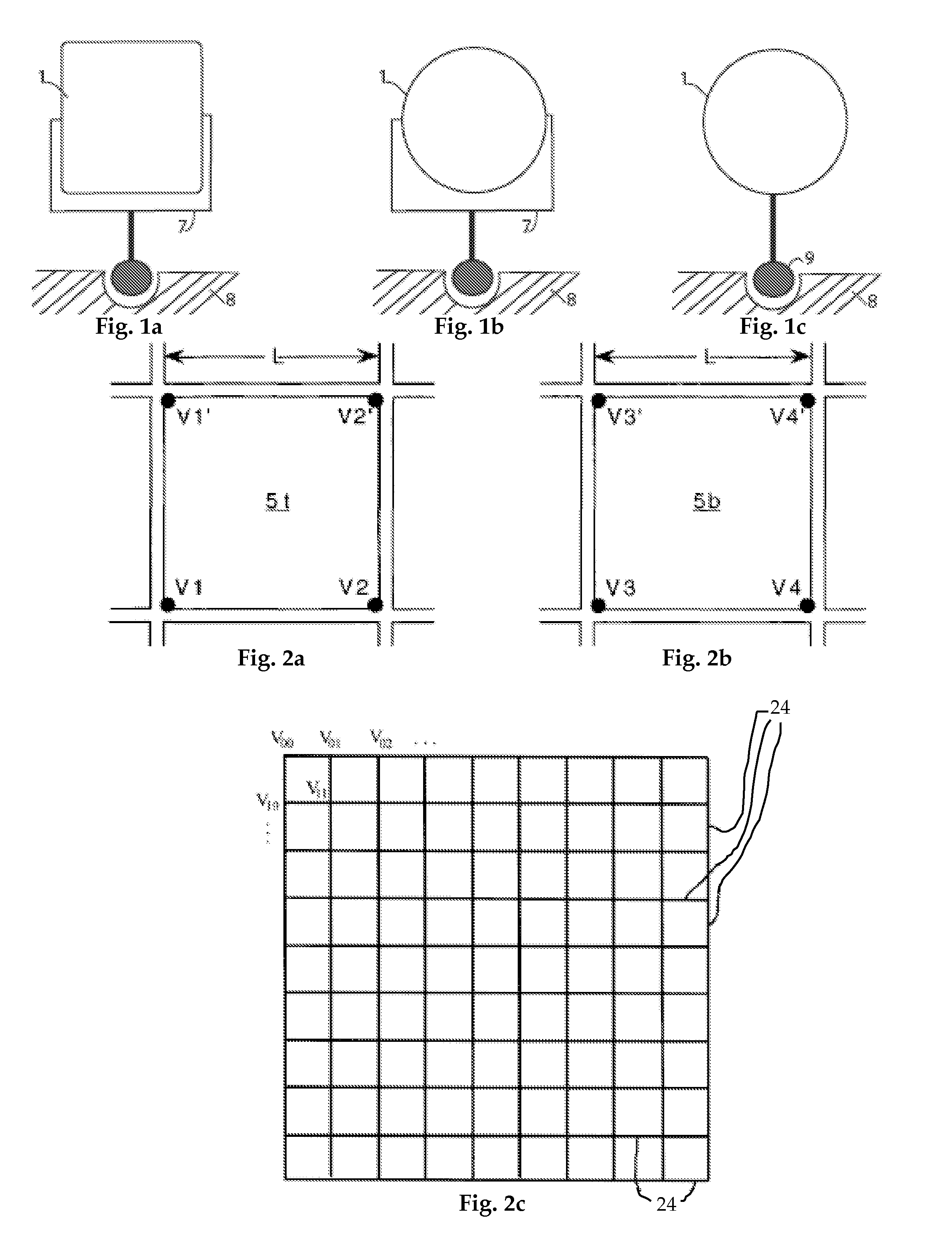
[0106]FIG. 1a is a front cross-sectional view of a rectangular optical element (mirror) 1 supported by gimbals 7, which are mounted on a support 8. This is one member of an adjustable Fresnel reflector solar concentrator array. The mirror can be flat or slightly concave.

[0107]FIG. 1...


PUM


Abstract

This invention deals with novel method and apparatus for positioning and motion control of the elements (mirrors) of a Fresnel reflector solar concentrator tracking heliostat array by induced and / or permanent dipole coupling to an electronic grid to produce angular deflection, and rotational motion. Thus forces and torques are produced without the use of internal moving parts. Control is achieved without recourse to magnetic fields, by means of high electric fields which may be attained at relatively low voltages. At low voltages, the instant invention exceeds the capability of conventional systems. It can perform dynamic motion control with independent amplitude and frequency modulation. It is ideally suited for maximization of solar energy focused by the array onto a receiver. Since there are no internal moving parts, the instant invention is the most adapted for fabrication from the mini- to the microtechnology realm. Furthermore it provides less costly and greater ease of manufacture from the mini- to the micro-realm.

Description

FIELD OF THE INVENTION[0001]The instant invention relates generally to a Solar Energy Concentrator Fresnel reflector array that tracks the sun and focuses the reflected light by means of induced dipole alignment of pivoted mirrors. The mirrors may be on a universal pivot that can rotate or tilt in any direction; or on gimbal pivots.BACKGROUND OF THE INVENTION[0002]This invention provides a better means to achieve affordable solar energy than by a conventional tracking heliostat array. In the latter, enabling the optical elements (mirrors) to be movable generally requires many large heavy motors that consume a great deal of power. This results in an expensive, bulky, and ponderous heliostat that is unfavorable for rooftop and other applications where much weight cannot be tolerated. The present invention functions in solar concentrators and similar equipment much the same as parabolic dish and parabolic trough concentrators, without their disadvantages of bulk and weight. The angular...

Claims


Application Information

Patent Timeline
Patent Type & Authority Applications(United States)
IPC IPC(8): H01L31/04G02B7/185
CPCF24J2/10H01L31/0547F24J2002/1066F24J2002/5437F24J2002/5489G02B7/183G02B26/0841Y02E10/47G02B19/0019F24J2/38G02B19/0042G02B19/0076Y02E10/52H02S20/00H01L31/0543F24J2/5431H02S20/30H02S40/22H02S20/10F24S2030/17F24S30/48F24S50/20F24S23/70F24S2023/85F24S2030/11
Inventor RABINOWITZ, MARIO
Owner RABINOWITZ MARIO
Why Eureka
Try Eureka