

Security element particularly for banknotes, security cards and the like, having Anti-counterfeiting features
- Summary
- Abstract
- Description
- Claims
- Application Information
AI Technical Summary
Benefits of technology
Problems solved by technology
Method used
Image

Examples
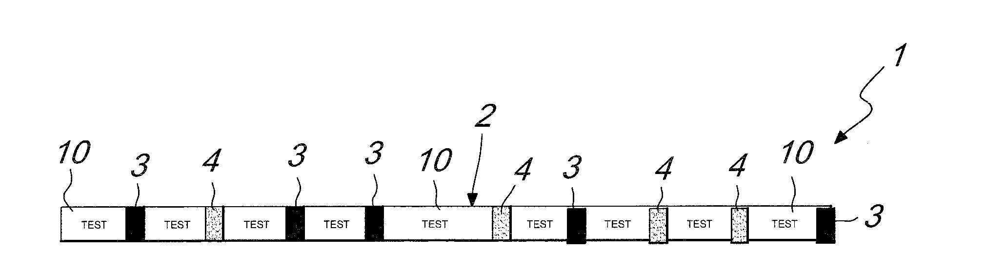
first embodiment
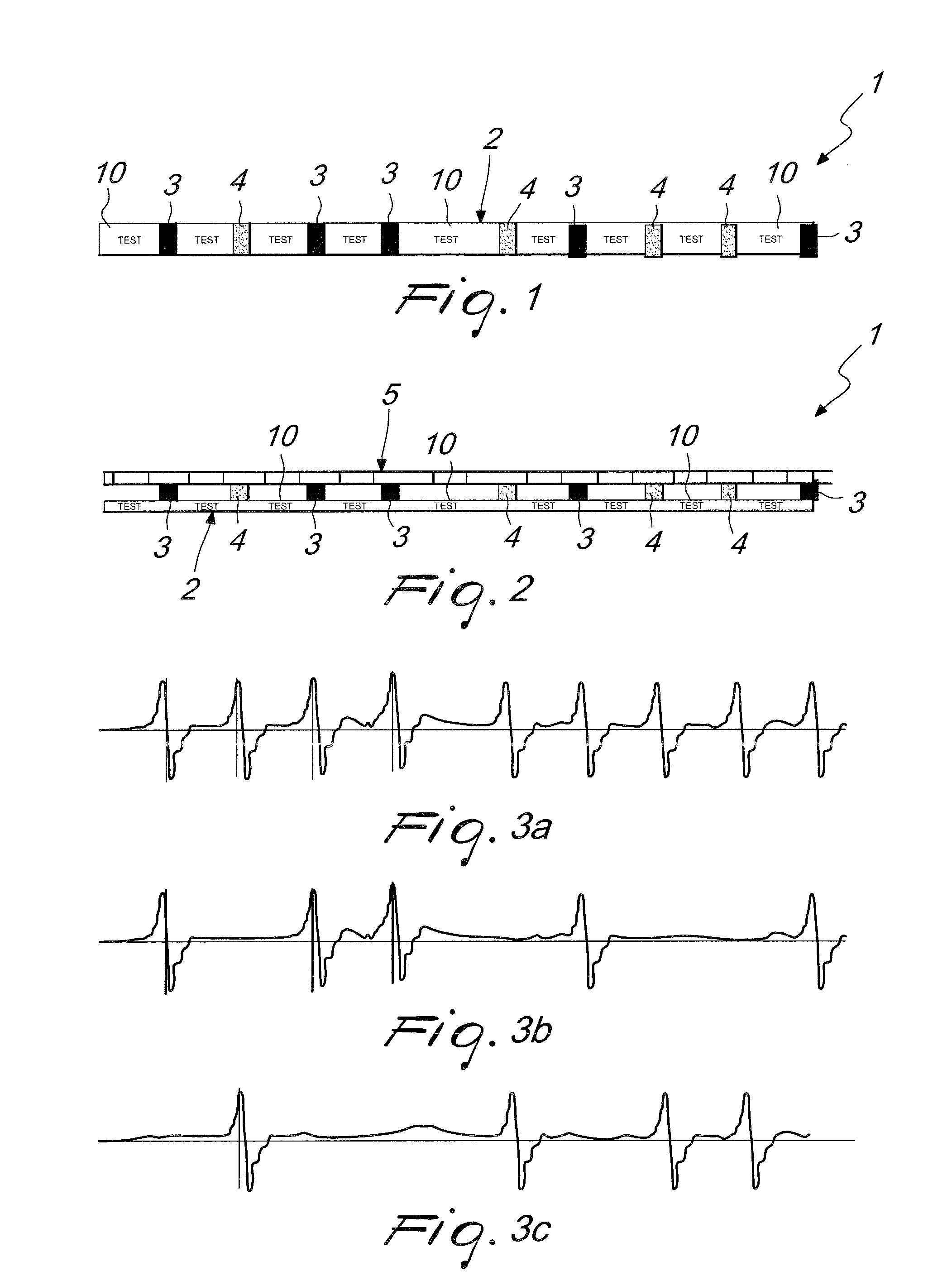
[0033]FIGS. 3a-3c plot respectively the signals which can be detected by a reading sensor, for a security element 1 according to FIGS. 1 and 2, in which FIG. 3a plots the signals that can be detected from all the magnetic areas 3, 4, FIG. 3b plots the signals that can be detected from the magnetic areas with high coercivity, and FIG. 3c plots the signals which can be detected from the magnetic areas with low coercivity.
[0034]Substantially, a security element, such as a security thread, has been provided which contains a first code generated by all the magnetic areas 3, 4 that are present (read by the first reading head), a second code generated only by the areas 3 with high coercive power (read by the second reading head), and a third code generated only by the areas 4 with low coercive power (the result of all the areas 3, 4 minus those with high coercive power 3). This is achieved by using for example the same value of residual magnetism both for the areas 4 with low coercive powe...
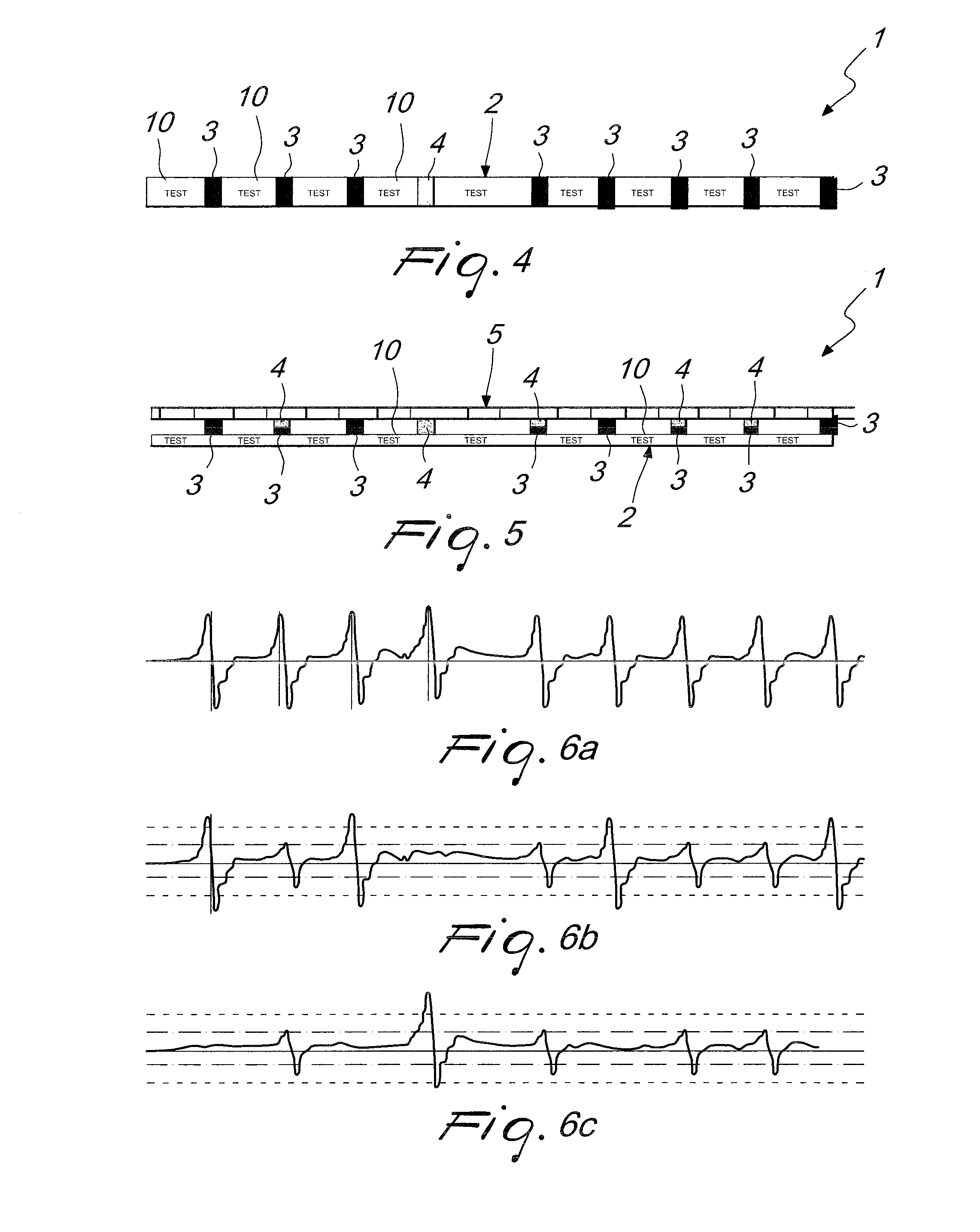
second embodiment
[0052]FIGS. 6a, 6b, 6c plot, in a manner similar to FIGS. 3a, 3b and 3c, the signals (codes) which can be detected by the security element provided according to the invention.
[0053]All the previously described threads provide for non-orientation of the magnetic direction of the magnetic ink during the transition from wet ink to dry ink which is characteristic of printing.
[0054]Further customizations can be performed for example by orienting the iron oxide which is used for the areas 3 and therefore has a high coercive power during printing, when it is still wet, then overmolding or coupling in register the magnetic areas 4 with tow coercive power. In this case, the magnetic areas 3 always have a north-south orientation, while the areas 4 can have a north-south or south-north orientation (180° rotation of magnetism) or are canceled out (for reading which is parallel to the thread), rotating the magnetism of the areas 4 only through 90 °.
[0055]In order to detect the codes thus provide...
PUM
 Abstract
Description
Claims
Application Information