Laminated stator core and method for manufacturing the same

Inactive Publication Date: 2010-12-30
MITSUI HIGH TEC INC
View PDF13 Cites 7 Cited by
  • Summary
  • Abstract
  • Description
  • Claims
  • Application Information

AI Technical Summary

Benefits of technology

[0026]The laminated stator core and manufacturing method thereof according to the present invention can simplify pressing processes and improve material yields, since both sides of the strip are used as one of the si

Problems solved by technology

However, the full blanking generates a lot of materi

Method used


Image

  • Laminated stator core and method for manufacturing the same
  • Laminated stator core and method for manufacturing the same
  • Laminated stator core and method for manufacturing the same

Examples


Embodiment Construction

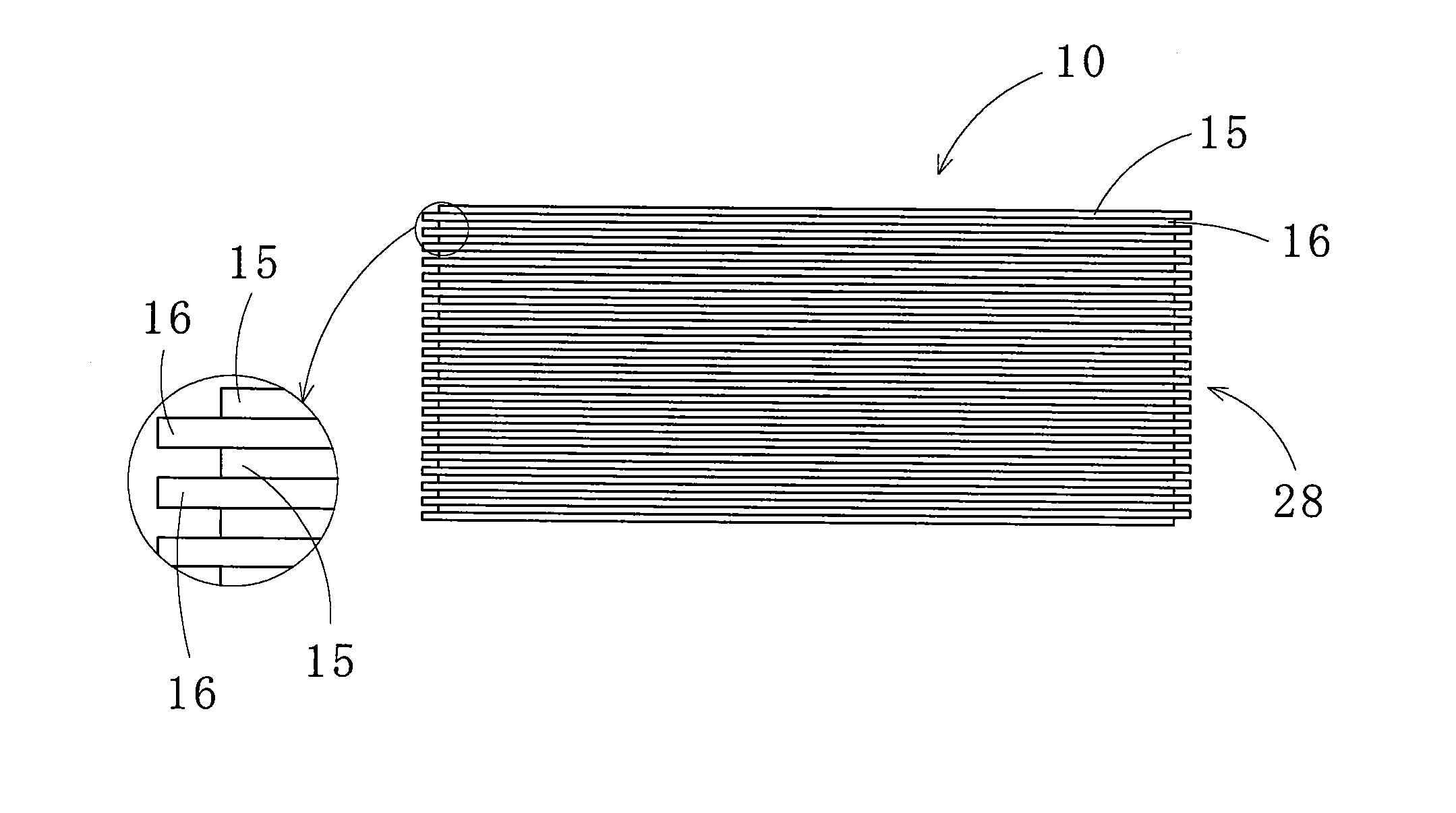
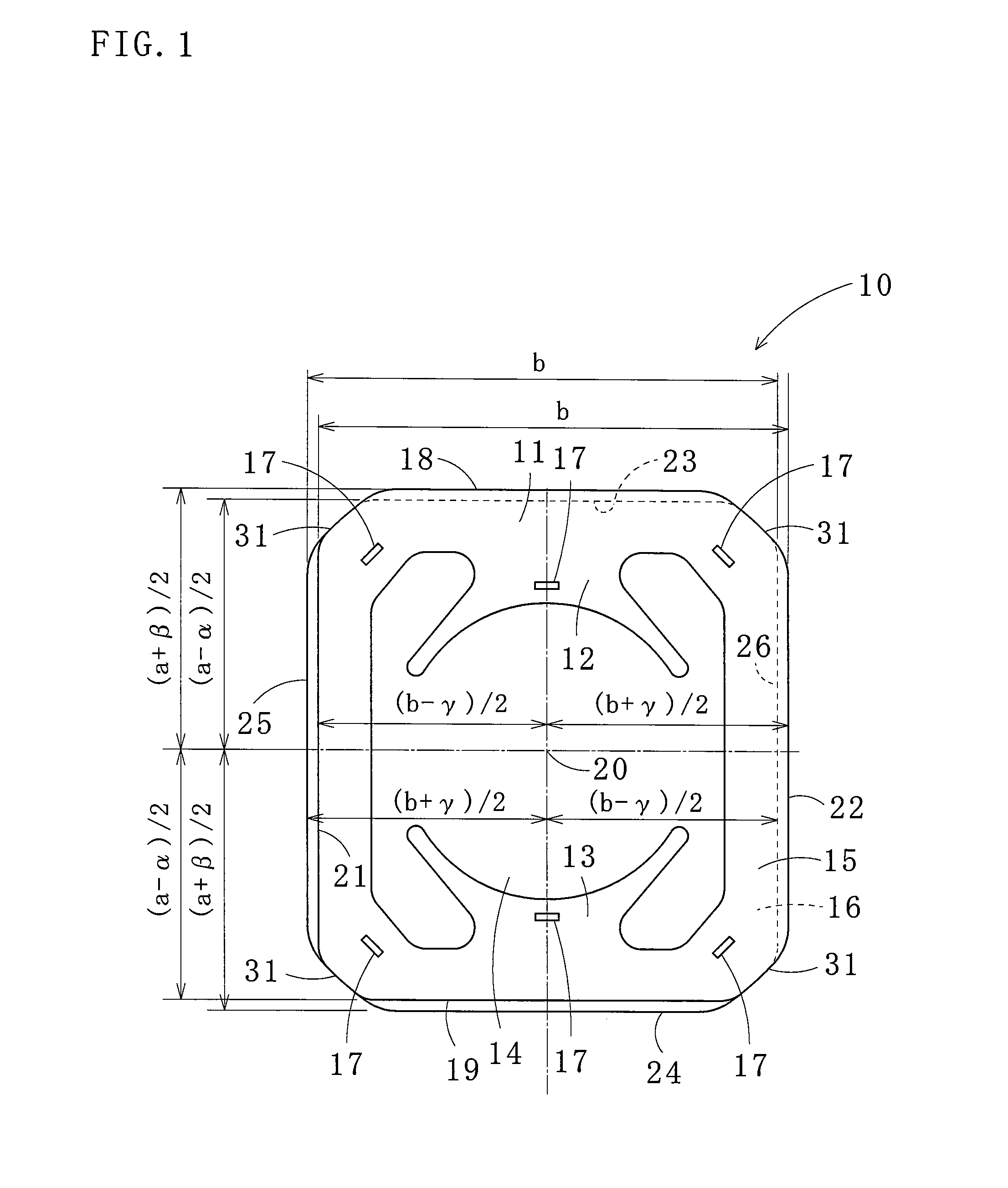
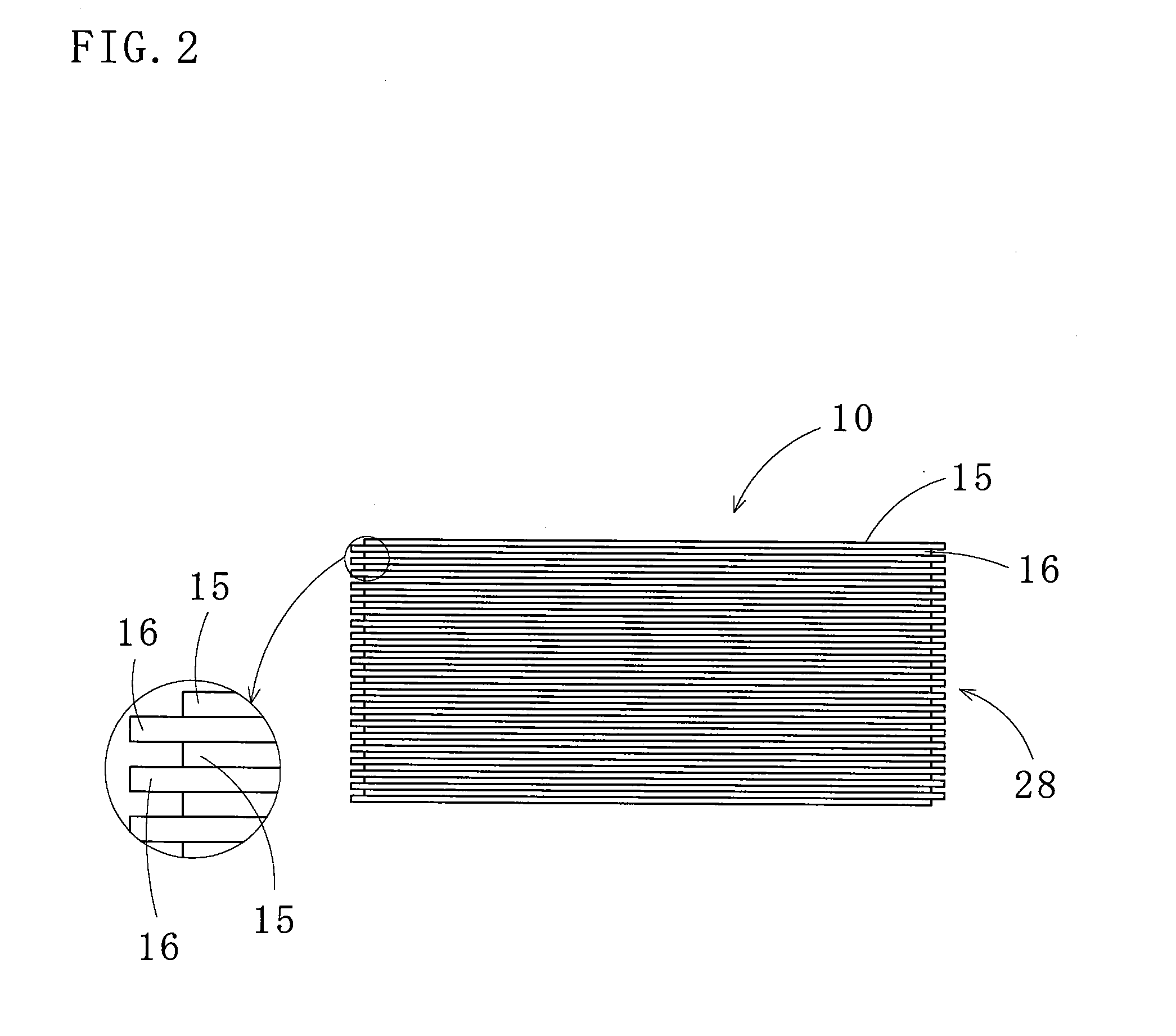
[0035]Referring to FIGS. 1 to 3, a laminated stator core 10 according to one embodiment of the present invention is described.

The laminated stator core 10 according to one embodiment of the present invention comprises: a yoke section 11; pole sections 12 and 13 formed inside the yoke section 11; and a rotor space 14 formed between the pole sections 12 and 13. An outline of the yoke section 11 is substantially rectangular shaped when viewed from the top. The rotor space 14 is circular shaped when viewed from the top. The laminated stator core 10 is rectangular shaped when viewed from the top and four corners thereof are rounded off. To form the laminated stator core 10, a plurality of core sheets 15 and 16 having a rectangular shape are sequentially and alternately laminated, and then caulked (interlocked) through caulking portions 17. In addition, a center 20 of the rotor space 14 is arranged vertically and laterally off-center from each center of the core sheets 15 and 16.

[0036]In ...


PUM

PropertyMeasurementUnit
Angleaaaaaaaaaa
Angleaaaaaaaaaa
Radiusaaaaaaaaaa

Abstract

A laminated stator core 10 and a manufacturing method thereof, the method including producing a plurality of core sheets 15 and 16 from a strip 33, ends 34 of the strip 33 being a part of a product without being cut twice, and rotating and laminating the core sheets. A laminated stator core formed by core sheets blanked from a magnetic strip, both ends of the magnetic strip being one of the sides of the core sheets, wherein the identically shaped core sheets each have a rotor space in the center thereof, each rotor space having a center located off-center in one direction with respect to each center of the core sheets, and the core sheets are rotated by a predetermined angle before being laminated with the rotor spaces vertically aligned.

Description

TECHNICAL FIELD[0001]The present invention relates to a laminated stator core and a method for manufacturing the same, capable of improving material yields and compensating variations in the thickness of a material strip.BACKGROUND ART[0002]To produce a laminated core, generally, core sheets having an identical shape are blanked from a material strip and interlocked with one another inside dies. In the blanking process, to compensate thickness deviations of the core sheets, the core sheets are rotated prior to being laminated. Also, outlines of the laminated core need to have rotational symmetries regardless of a rotational angle of the core sheets. As for a blank layout, full blanking (blanking a whole outline at a time) is generally used. However, the full blanking generates a lot of material scraps, resulting in poor yields of the material. Patent Documents 1 and 2 employ a scrapless blanking as the blank layout to improve material yields and a multiline alignment of the core she...

Claims


Application Information

Patent Timeline
IPC IPC(8): H02K1/12H02K15/00
CPCH02K1/146H02K1/16H02K5/18Y10T29/49009H02K15/024B21D28/06B21D43/02H02K15/022
Inventor UMEDA, KAZUHIKONAKAMURA, SHUICHIIWATA, KENICHIRO
Owner MITSUI HIGH TEC INC
Why Eureka
Try Eureka