
Method, apparatus and system for dynamic range estimation of imaged scenes

a dynamic range estimation and image processing technology, applied in the field of image processing methods, apparatuses and systems for dynamic range estimation of imaged scenes, can solve the problems of limiting the dynamic range of digital images, darkening, and noisy pictures

Active Publication Date: 2010-12-30
MICRON TECH INC
View PDF18 Cites 32 Cited by
  • Summary
  • Abstract
  • Description
  • Claims
  • Application Information

AI Technical Summary

Benefits of technology

This approach enables the camera to capture and process luminance information beyond its usual limits, preventing clipping and allowing for more accurate exposure settings, even in scenes with rapidly changing illumination, thereby improving the dynamic range and maintaining image quality.

Problems solved by technology

However, pixel saturation, analog-to-digital saturation, exposure, gain settings and bit width processing limitations in an imaging device can limit the dynamic range of a digital image.
Generally, using higher gains and longer exposures result in the brightest areas of a scene being clipped.
On the other hand, using lower gains and shorter exposures result in darker, noisier pictures.
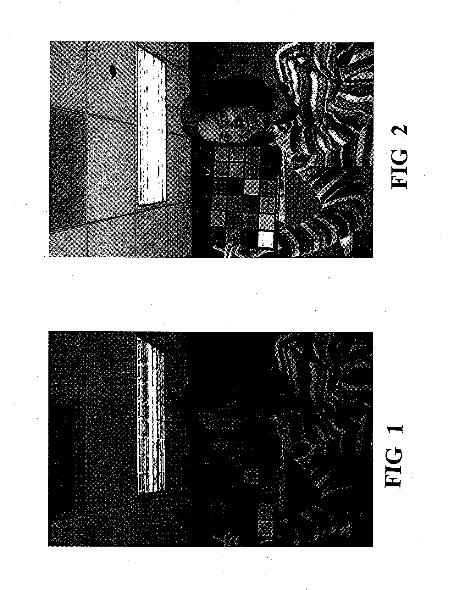
Merely increasing the exposure period may more correctly expose the person but would lead to brightness clipping and loss of detail of the lamp, as shown in FIG. 2.
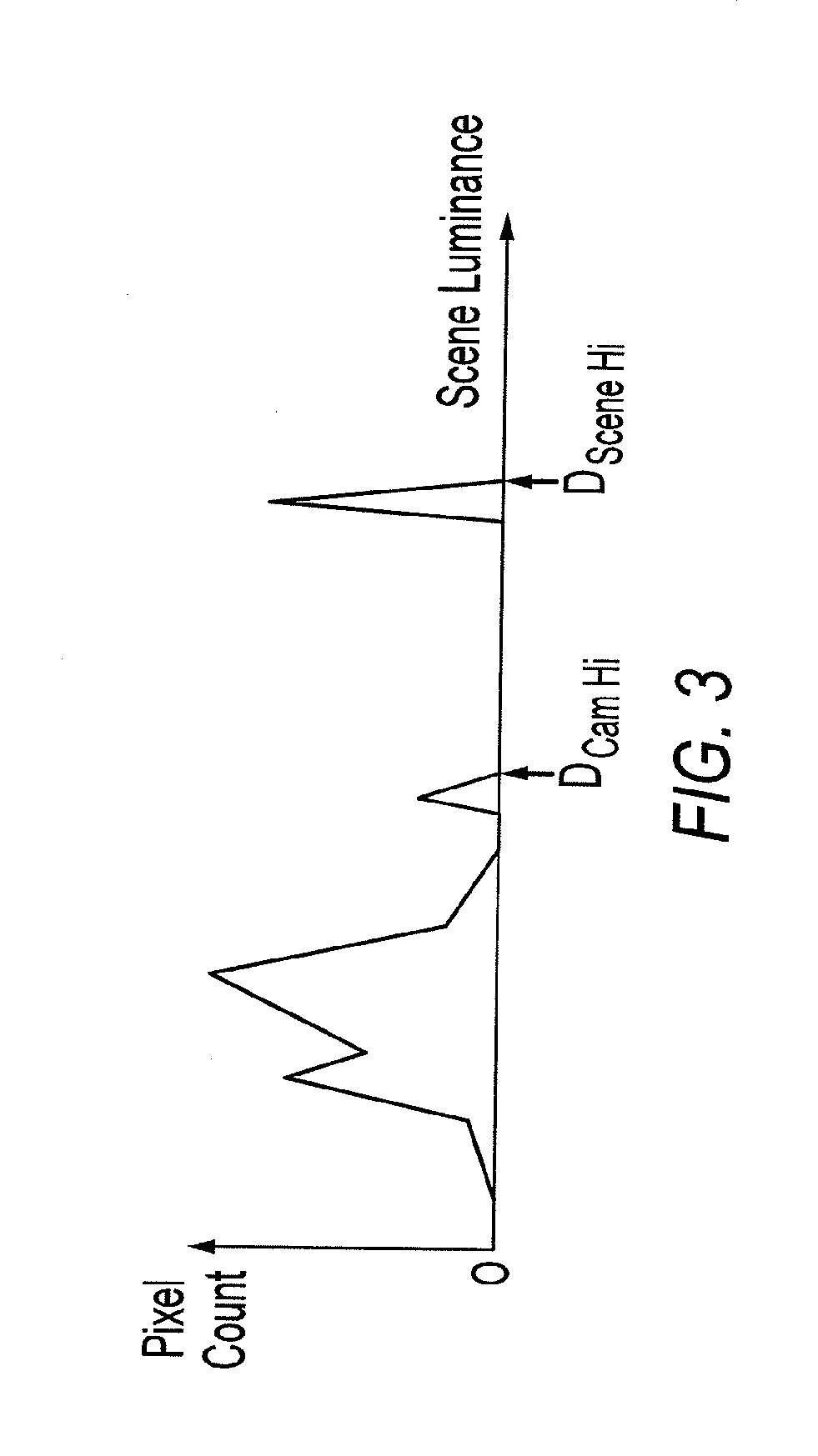
Thus, luminance that corresponds to a pixel value above 1023 LSB is clipped to 1023 LSB, resulting in a loss of information.
Additionally, when scene illumination changes rapidly, the rapid increase in scene luminance may exceed DCam HI and saturate the image output, thereby resulting in a loss of information on scene brightness to the auto-exposure module.
While the camera phone is lying on the table, the camera lens faces the table surface and the luminance of the table is very low so that the auto-exposure module sets a long exposure time.
The excessive illumination causes the image to saturate and become clipped.
Consequently, the auto-exposure module has insufficient information on the actual brightness of the scene and cannot accurately determine the appropriate exposure for the image.

Method used


Image

  • Method, apparatus and system for dynamic range estimation of imaged scenes
  • Method, apparatus and system for dynamic range estimation of imaged scenes
  • Method, apparatus and system for dynamic range estimation of imaged scenes

Examples


Embodiment Construction

[0016]Disclosed embodiments relate to a method, apparatus and system for dynamic range estimation of imaged scenes and use of the estimated dynamic range in auto-exposure operations. Embodiments discussed herein enable a camera to sense and process luminance information beyond DCam HI, the highest luminance value available in an image processing pipeline. Typically, luminance information exceeding DCam Hi may be present in the pixel signals, but is lost during gain operations, for example, during lens vignetting correction and white point correction. However, gain stages in the image processing pipeline are modified to process pixel luminance values having a dynamic range beyond the DCam HI, luminance value which can be processed by the image processing pipeline. Luminance values with increased dynamic range are provided to a camera auto-exposure module which enables a quicker reaction to changes in luminance values.

[0017]Some embodiments described herein cause the intentional under...


PUM


Abstract

A method, apparatus, and system for dynamic range estimation of imaged scenes for automatic exposure control. For a given exposure time setting, certain areas of a scene may be brighter than what a camera can capture. In cameras, including those experiencing substantial lens vignetting, a gain stage may be used to extend dynamic range and extract auto-exposure data from the extended dynamic range. Alternatively, dynamic range can be extended using pre-capture image information taken under reduced exposure conditions.

Description

FIELD OF THE INVENTION[0001]Disclosed embodiments relate generally to an image processing method, apparatus, and system for dynamic range estimation of imaged scenes.BACKGROUND OF THE INVENTION[0002]Ideally, digital images created through the use of CMOS and other solid state image sensors are exact duplications of the imaged scene projected upon the image sensor arrays. However, pixel saturation, analog-to-digital saturation, exposure, gain settings and bit width processing limitations in an imaging device can limit the dynamic range of a digital image.[0003]To achieve a more realistic photographic image, an automatic camera must choose an appropriate exposure time and gain setting for image pixel signals using available dynamic range information. Generally, using higher gains and longer exposures result in the brightest areas of a scene being clipped. On the other hand, using lower gains and shorter exposures result in darker, noisier pictures. Therefore, to choose an optimal expo...

Claims


Application Information

Patent Timeline
Patent Type & Authority Applications(United States)
IPC IPC(8): H04N5/235H04N23/75
CPCG03B7/08
Inventor OVSIANNIKOV, ILIA
Owner MICRON TECH INC
Learn More