Switched-capacitor regulators

a technology of switch-capacitor and regulator, which is applied in the direction of power conversion systems, dc-dc conversion, instruments, etc., can solve the problems of increasing increasing the accuracy of the switch-capacitor, and increasing the chip area and manufacturing costs. , to achieve the effect of improving the loop-gain magnitude, improving the efficiency of the area, and improving the regulation of line and load

Active Publication Date: 2008-05-20
THE HONG KONG UNIV OF SCI & TECH
View PDF15 Cites 44 Cited by
  • Summary
  • Abstract
  • Description
  • Claims
  • Application Information

AI Technical Summary

Benefits of technology

[0011]Usually an additional power transistor is required to regulate the output voltage of a switched-capacitor regulator. By means of the present invention, a switched-capacitor regulator operates in pseudo-continuous regulator mode using three-stage switchable opamps with time-multiplexed pole-splitting compensation technique. The regulator controls the output voltage continuously during every capacitor-discharging phase without adding extra power transistor nor requiring high-voltage clock signals; thereby enhancing area efficiency. In addition, the use of three-stage switchable opamps increases loop-gain magnitude and improves line and load regulations by alternate switching of gain stage in different clock phases. The time-multiplexed pole-splitting compensation technique in the switchable opamp not only ensures stability but also reduces load-transient recovery time.
[0012]The switched-capacitor regulator according to the present invention decreases chip area and results in a comparatively low output ripple at low switching frequencies; which can improve the accuracy of the resulting output voltage.

Problems solved by technology

These increase the chip area of the thereby increasing the manufacturing cost.
Existing implementations employ single-stage linear amplifier in the controller, which can affect the accuracy of the regulators.
However, the additional circuitry is implemented by power transistors; thereby increasing the chip area and manufacturing cost.
Therefore, the area efficiency of the switched-capacitor regulator is not ideal
Extra power transistors are still required for regulating the output voltage, and this lowers the area efficiency of the regulator.
In addition, since the gate-voltage swing of Ml4 and Mr4 is 2VDD and increases with the input supply voltage, the SLDR control causes switching noise problems in the switched capacitor regulator.
Two-stage switchable opamps may not provide sufficient loop gain magnitude, and hence the accuracy of the switched capacitor regulator is not optimized.

Method used


Image

  • Switched-capacitor regulators
  • Switched-capacitor regulators
  • Switched-capacitor regulators

Examples


Embodiment Construction

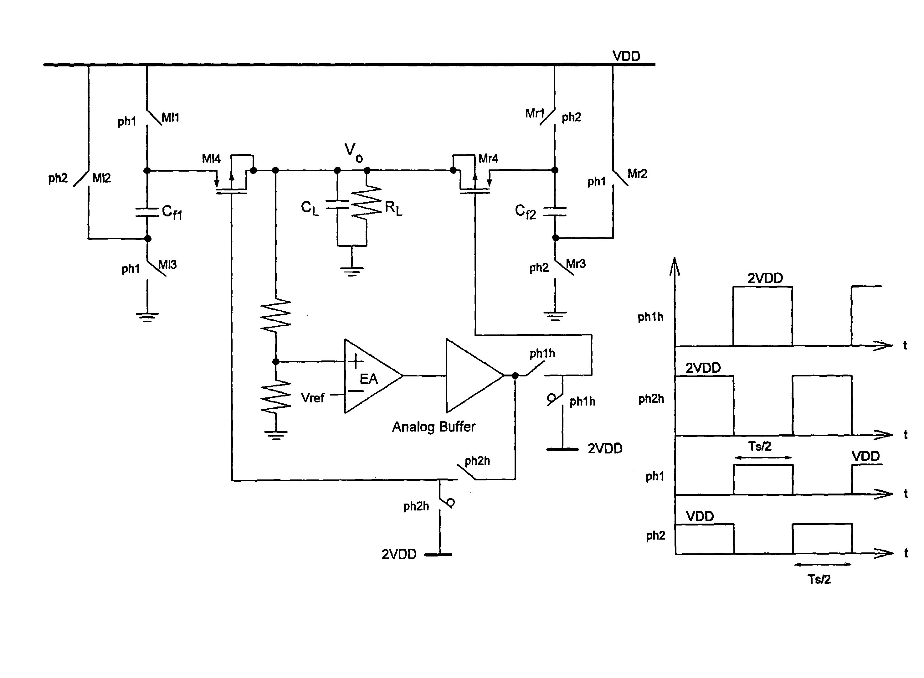
[0031]The present invention is based on the concept of pseudo-continuous control switched-capacitor regulator. FIG. 6 shows an embodiment of the structure of the regulated cross-coupled voltage doubler with pseudo-continuous control. In the cross-coupled power stage, there are eight power transistors Ml1-Ml4 and Mr1-Mr4, and two flying capacitors Cf1 and Cf2 for voltage conversion. The additional circuitries Mal, Mar, Ral and Rar are used to reduce both the shoot-through current and switching noise of the converter, while the increase in area due to the additional circuitries is insignificant, as disclosed in H. Lee and P. K. T. Mok, “Switching Noise Reduction Techniques for Switched-Capacitor Voltage Doubler,” Proceedings of the IEEE 2003 Custom Integrated Circuits Conference, pp. 693-696, 2003. With pseudo-continuous control, both Ml2 and Mr2 operate as regulation transistors (also referred to as regulation switches), while other power transistors function as switches, therefore n...


PUM


Abstract

A switched-capacitor regulator is provided for regulating the output voltage of a voltage supply. The switched-capacitor regulator includes a supply input terminal capable of receiving a supply voltage, two or more flying capacitors, a regulation switch located between each flying capacitor and the supply input terminal, and a voltage control circuit. The activity of the regulation switches is controlled by the voltage control circuit. In one embodiment of the invention, the voltage control circuit includes a feedback resistance area having one or more feedback resistors located between the output of the flying capacitors and a ground terminal, a first gain stage connected to the feedback resistance area, and two or more second switchable gain stages, which are each connected to a regulation switch and the first gain stage. The switched-capacitor regulator operates in pseudo-continuous regulator mode using three-stage switchable operational amplifiers with time-multiplexed pole-splitting compensation.

Description

CROSS-REFERENCE TO RELATED APPLICATIONS[0001]This application claims priority from U.S. Provisional Application No. 60 / 645,966, filed Jan. 24, 2005, entitled AN AREA-EFFICIENT AND HIGH-ACCURACY SWITCHED-CAPACITOR REGULATOR. This Provisional Application is hereby incorporated herein by reference in its entirety.FIELD OF THE INVENTION[0002]The invention relates to switched-capacitor regulators, and in particular to switched-capacitor regulators with pseudo-continuous output regulation using a three-stage switchable operational amplifier and time-multiplexed pole-splitting compensation techniques. The invention is useful for decreasing chip area and improving the accuracy of output voltage.BACKGROUND OF THE INVENTION[0003]Switched-capacitor regulators are needed in many portable electronic devices to provide supply voltages for different systems. Possible devices include personal digital assistants, notebook computers and mobile phones.[0004]The importance of switched-capacitor regulat...

Claims


Application Information

Patent Timeline
Patent Type & Authority Patents(United States)
IPC IPC(8): H02M7/00
CPCH02M3/07
Inventor MOK, KWOK TAI PHILIPLEE, HOI
Owner THE HONG KONG UNIV OF SCI & TECH
Why Eureka
Try Eureka