
Method and device for displaying the surroundings of a vehicle

a vehicle and surroundings technology, applied in the field of vehicles surroundings, can solve the problems of high computational power, achieve the effect of reducing the number of vehicles, facilitating instantaneous surroundings, and ensuring the accuracy of detail

Inactive Publication Date: 2010-12-30
ROBERT BOSCH GMBH
View PDF19 Cites 36 Cited by
  • Summary
  • Abstract
  • Description
  • Claims
  • Application Information

AI Technical Summary

Benefits of technology

[0005]The method according to the present invention provides that in each case a surroundings image from a given surrounding area is ascertained by the detection sensor in different vehicle positions, and / or at least one surroundings image from the given surrounding area is ascertained in each case by at least two detection sensors situated at a distance from one another, in each case a composite surroundings image being obtained from the surroundings images and displayed by the display device. Thus, on the one hand it is provided that a surroundings image from a given surrounding area is ascertained in each case in different vehicle positions, for example while driving the vehicle, using a detection sensor. Due to the fact that the given surrounding area is detected from two different vehicle positions with the aid of the detection sensor, the surrounding area is “observed” from different angles / perspectives, thus generating different surroundings images which record the surrounding area from different sides. A composite surroundings image is then obtained from these images by combining the information which may be extracted from the particular surroundings images to form a surroundings image. By observing the surrounding area from different viewing angles it is thus possible to detect not only the closest objects, but also objects situated behind same, and to accordingly display these using the display device of the vehicle. Alternatively or additionally, it is provided that when the vehicle is at a standstill or is traveling, surroundings images from the given surrounding area are detected from different “viewing angles,” using at least two detection sensors situated at a distance from one another. This has the same effect as the above-described detection of the surrounding area from two different vehicle positions using one detection sensor, for example while driving. The use of multiple detection sensors has the advantage that the composite surroundings image combined from the surroundings images may be obtained even when the vehicle is at a standstill. In addition, the composite surroundings image may be obtained much more quickly, since the given surrounding area may be simultaneously detected from different perspectives. With the aid of multiple detection sensors it is also possible to easily display the instantaneous surroundings of the vehicle, including the closest objects as well as objects situated behind same. The composite surroundings image advantageously results in a surroundings map which illustrates the surroundings of the vehicle with particular accuracy of detail, preferably in a top view of the vehicle.
[0011]It is advantageously provided that at least one detection sensor is oriented essentially perpendicularly to the longitudinal axis of the vehicle. Four detection sensors are typically mounted in the front end and / or four detection sensors are typically mounted in the rear end of the vehicle, which are essentially oriented toward the front or the rear, respectively. For detecting the surroundings of the vehicle while driving, these detection sensors are also sufficient for detecting objects located laterally to the vehicle. However, when the vehicle is at a standstill it is advantageous when at least one additional detection sensor on at least one side of the vehicle is oriented essentially perpendicularly to the longitudinal axis of the vehicle. Thus, even when the vehicle is at a standstill, objects located next to the vehicle may be detected and displayed to the driver with the aid of the display device. In principle, of course, it is possible to increase the number of detection sensors used in order to obtain an even more detailed surroundings image. Likewise, the number of detection sensors may be reduced. When ultrasonic sensors are used, the distances from objects are computed in a known manner by triangulation of neighboring sensor signals. By observing the surrounding area from different viewing angles it is possible, as previously stated, to ascertain not only distances from objects but also the shape of the objects. Thus, for example, a differentiation may be made between a continuous wall and a post, or a row of posts.

Problems solved by technology

However, this requires high computational power, and also allows only the surroundings image / range of the surroundings detected by the camera at the moment to be displayed.

Method used


Image

  • Method and device for displaying the surroundings of a vehicle
  • Method and device for displaying the surroundings of a vehicle

Examples


Embodiment Construction

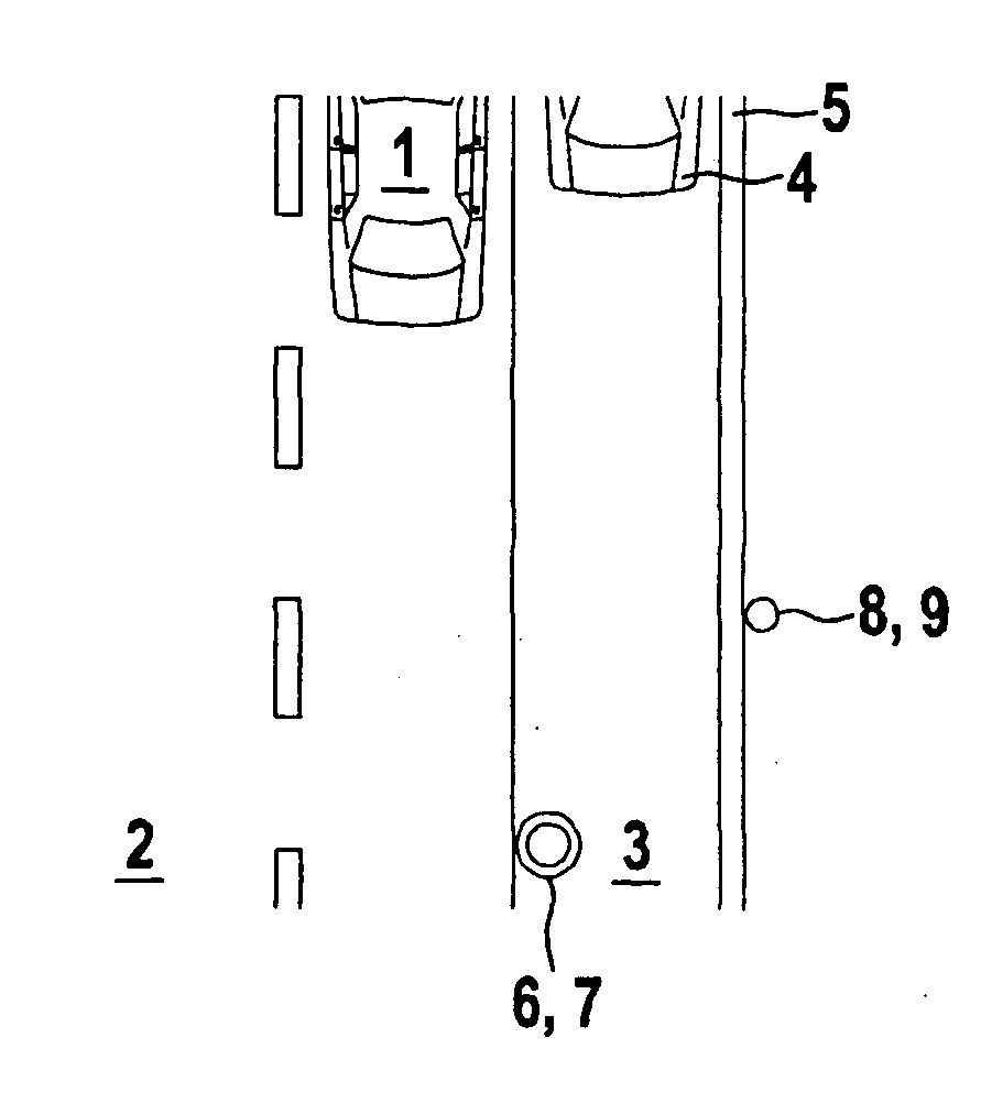
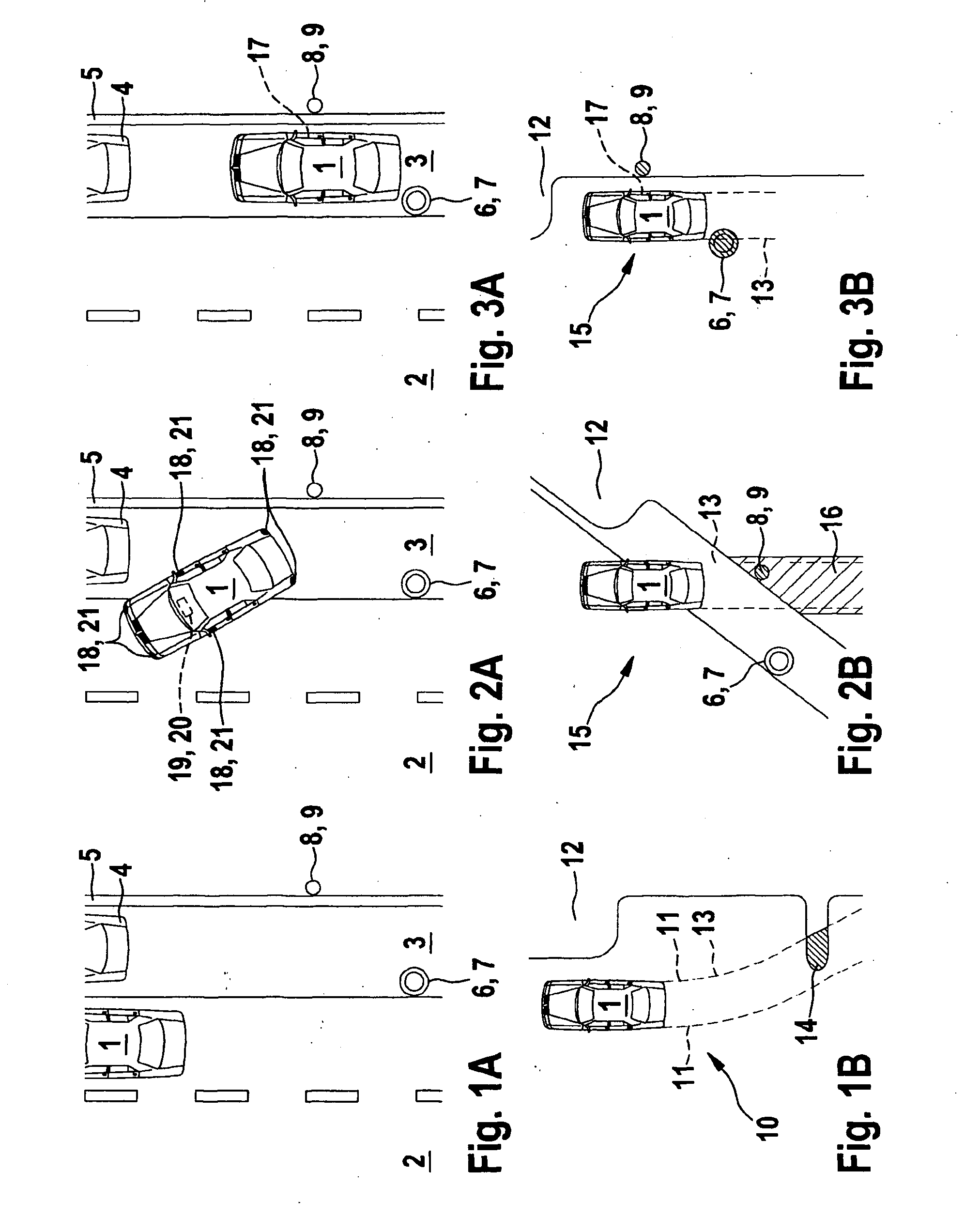
[0028]FIG. 1A shows a top view of a traffic situation with a vehicle 1 which is located on a roadway 2. On its right side, viewed in the direction of travel of vehicle 1, roadway 2 has a shoulder, i.e., a parking lane 3, on which a vehicle 4 is parked. Parking lane 3 is bordered on its right side by a curb 5. An object 6 designed as a post 7 is situated on parking lane 3, near roadway 2 and at a distance from parked vehicle 4. An object 8 designed as a pole 9, for example for a street light, is situated near curb 5 between parked vehicle 4 and post 7, on the side of curb 5 opposite from parking lane 3. The driver of vehicle 1 then intends to park in the parking space between parked vehicle 4 and post 7.

[0029]FIG. 1B shows the display of a display device for displaying the surroundings of vehicle 1. A surroundings image 10 from a given surrounding area of vehicle 1 is ascertained in each case in different positions of vehicle 1, using a detection sensor. This may be carried out, for ...


PUM


Abstract

In a method for displaying on a display device the surroundings of a vehicle, the surroundings are detected by at least one detection sensor as an image of the surroundings while the vehicle is traveling or at a standstill. A surroundings image from a given surrounding area is ascertained by the detection sensor in different vehicle positions, and / or at least one surroundings image from the given surrounding area is ascertained by each of at least two detection sensors situated at a distance from one another, and in each case a composite surroundings image is obtained from the surroundings images and displayed by the display device.

Description

BACKGROUND OF THE INVENTION[0001]1. Field of the Invention[0002]The present invention relates to a method and device for displaying the surroundings of a vehicle, in particular a motor vehicle, using at least one display device of the vehicle, the surroundings being detected by at least one detection sensor as an image of the surroundings while the vehicle is traveling or at a standstill.[0003]2. Description of Related Art[0004]Methods and devices of the aforementioned type are known from the related art. These methods and devices are often used in conjunction with parking assistance systems of motor vehicles, in which, in order to simplify the parking operation, the immediate surroundings are displayed to the driver, via a colored display of the critical distances from the vehicle, on a display device of the vehicle. For this purpose the immediate surroundings of the vehicle are detected using a detection sensor, only the objects or contours of these objects detected at the moment ...

Claims


Application Information

Patent Timeline
IPC IPC(8): G06K9/00G08G1/04H04N7/18G01S15/931G01S15/86
CPCB62D15/0275G01S15/025G01S2015/935G01S2013/9314G01S15/931G01S15/86
Inventor SCHMID, ROLAND
Owner ROBERT BOSCH GMBH
Learn More