Leaching chamber family with common end connectors

Active Publication Date: 2010-12-30
INFILTRATOR WATER TECH LLC
View PDF8 Cites 4 Cited by
  • Summary
  • Abstract
  • Description
  • Claims
  • Application Information

AI Technical Summary

Benefits of technology

[0010]An object of the invention is to provide means for interconnecting chambers of different sizes and for reducing the number of different end closures and the like associated with a family of chambers. An further object of the invention is to provide a light weight molded plastic chamber for receiving and dispersing wastewater or stormwater, or for draining soils, where the chamber has good strength, good leaching area per unit length, and good storage volume per unit length, while at the same time efficiently using plastic material. A still further object is to provide a leaching chamber which has a low profile along with the foregoing features.
[0011]In accord with embodiments of the invention, when a group of chambers comprises a family which has different profiles and or different widths, each chamber in the group has a common-size end connector. Thus, a string of mixed size chambers can be assembled. And the number of accessories, such as end caps and couplers which mate with the connectors, that an installer has to carry in inventory, is reduced. Preferably, the height of end connectors within a family is no greater than the height of the top of the smallest chamber in the family. Preferably, the send connectors interconnect by overlap and underlap and permit rotational adjustment in the horizontal plane.
[0014]The shape of the chamber wall and open top pillar(s) enable the chambers to stack in closely nested fashion, for economic shipment. To better enable removal of a first chamber from the top of a stack of nested chambers, in some chamber embodiments the pillar and the terminal ends of any interrupted peak and or valley corrugation are shaped so that an installer may manually lift one base flange of the chamber upwardly, to rotate the chamber about the opposing side base flange.
[0016]In some embodiments of the invention, the pillar bases provide between 4 and 15 percent, and up to 25 percent, of the total bearing area of the chamber, for supporting the chamber on soil; and, the masking of the underlying soil that results from the pillar bases is only a small percent of the leaching area of the chamber. Thus, the benefits which the one or more pillars provide are achieved without greatly compromising leaching area.
[0018]The unique corrugation width relationships enable more corrugations per unit length which increases strength, and they increase the amount of storage area and leaching area per unit length of chamber, compared to comparable chambers which have corrugations. Chambers having pillars and or the specially proportioned corrugation widths may have closed ends or open ends, with and without connectors for mating with other chambers. The corrugation width features may be used with or without pillars. The pillar features may be used in chambers without the corrugation width features.
[0019]Exemplary chambers in accord with the invention are able to meet industry performance standards. They are strong, economically made, and economically transported and stored due to good stacking characteristics. Exemplary chambers have a combination of low profile and good strength, together with high storage volume, low plastic weight and high leaching area, all per unit length of chamber. Exemplary chambers may be made by different plastic forming means.

Problems solved by technology

In alternative chamber embodiments, the connectors overlap-underlap but do not enable pivoting in the horizontal plane.
Among other reasons, such ribs may increase stacking height.

Method used


Image

  • Leaching chamber family with common end connectors
  • Leaching chamber family with common end connectors
  • Leaching chamber family with common end connectors

Examples


Embodiment Construction

[0047]This application is related to U.S. provisional applications No. 61 / 269,880, filed Jun. 29, 2009, and No. 61 / 396,524, filed May 28, 2010, the disclosures of which are incorporated herein by reference in their entireties.

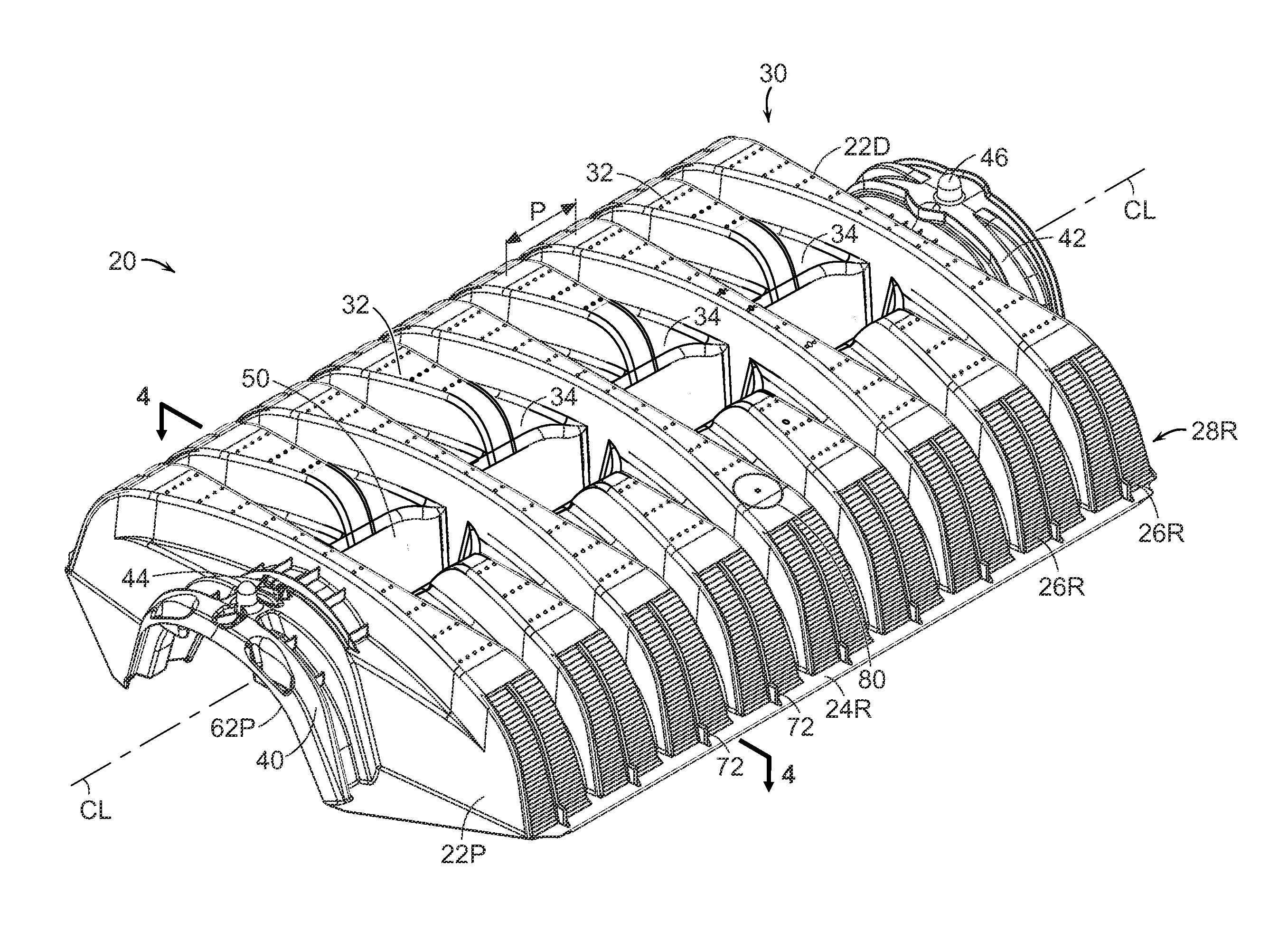
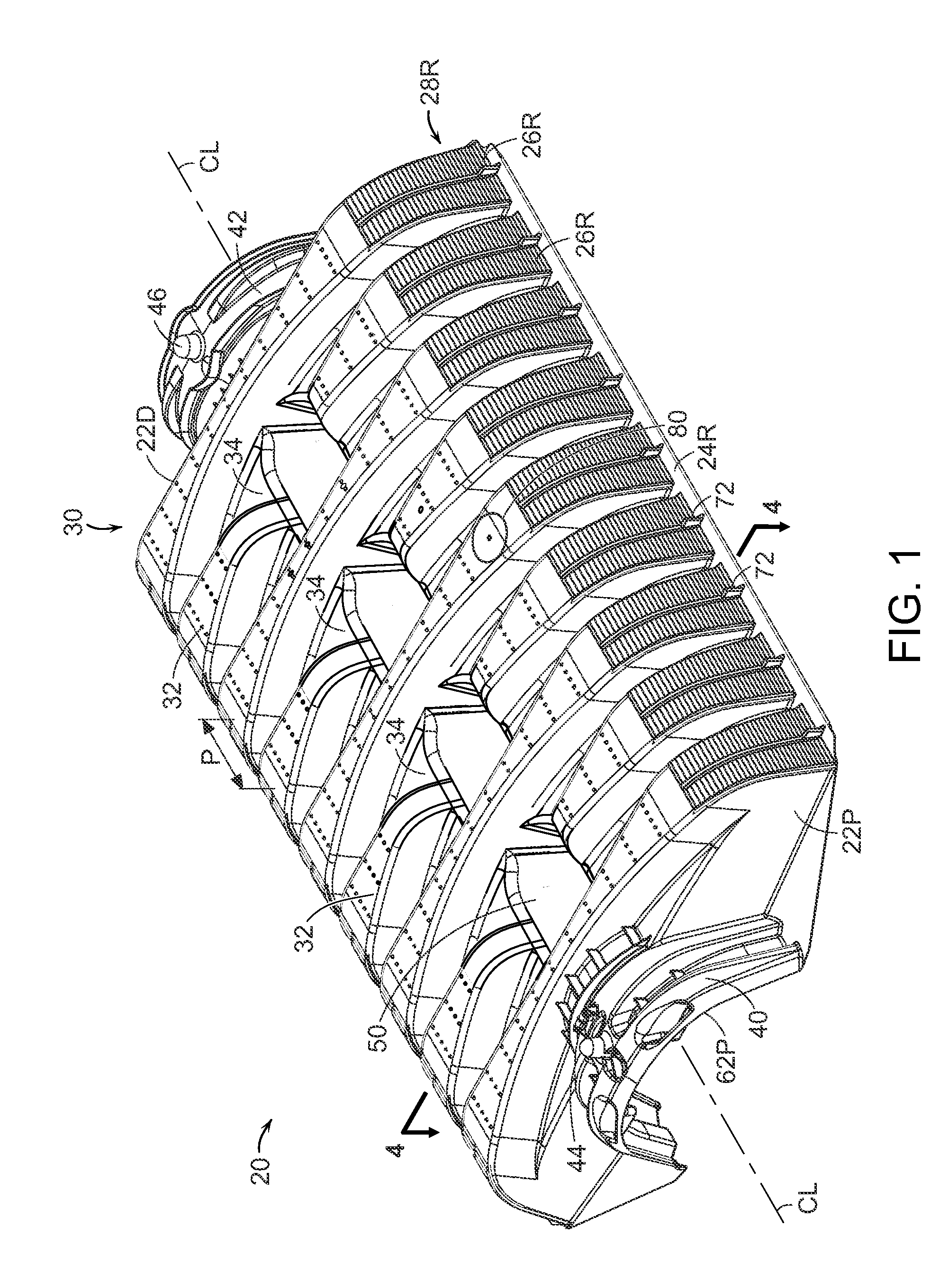
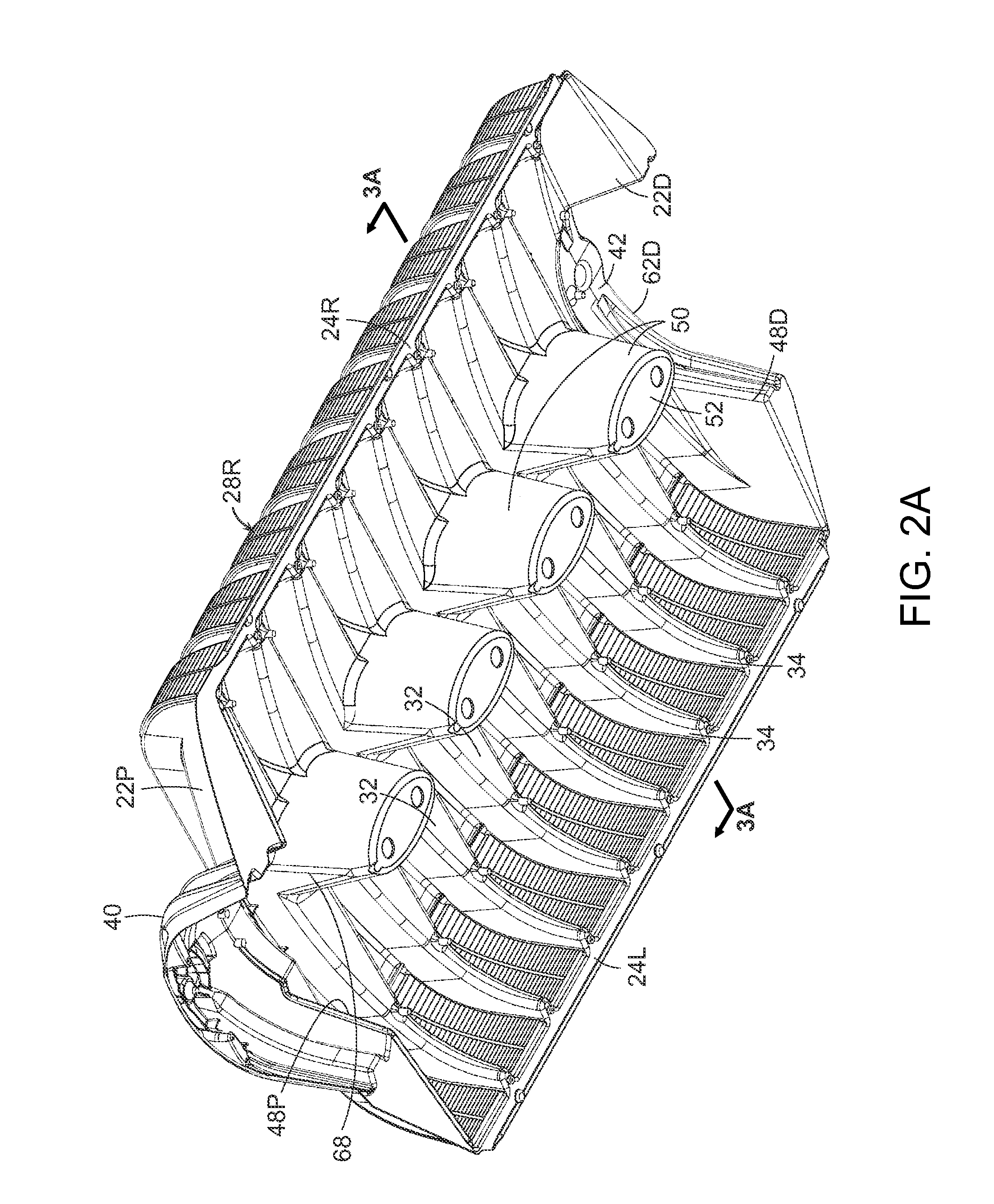
[0048]The present invention is described in terms of a thermoplastic leaching chamber. FIGS. 1 and 2A show an injection molded thermoplastic chamber 20 in oblique view, respectively looking down on the top of the chamber and up at the bottom of the chamber. FIG. 3A is a simplified transverse vertical plane projected cross section of the chamber, through one of the center pillars. An exemplary chamber 20 may have a base width W of about 34 inches and a height H of about eight inches. The length L of the chamber is nominally 48 inches. The actual overall length is about 52 inches, so that when chambers are overlapped by means of their end connectors, each chamber contributes about 48 inches to the length of a string of chambers. The foregoing shorter dimension, i...


PUM


Abstract

In a family of plastic leaching chambers, each having an arch shape cross section and corrugations, there are chambers of different top heights and possibly different widths. Each chamber has a common size of end connector, so chambers within the family, of any size, can be interconnected. Preferably, the height of an end connector is no more than the top height of the smallest chamber in the family. Preferred chambers have one or more hollow pillars extending downwardly within the interior of the chamber; and preferred chambers have peak corrugations which are substantially wider than the intervening valley corrugations.

Description

CROSS-REFERENCE TO RELATED APPLICATIONS[0001]This application claims the benefit under 35 U.S.C. §119(e) of U.S. provisional application No. 61 / 396,524, filed May 28, 2010, and U.S. provisional application No. 61 / 269,880, filed Jun. 29, 2009, the disclosures of which are incorporated herein by reference in their entireties.TECHNICAL FIELD[0002]The present invention relates to apparatus for collecting, receiving, detaining or dispersing liquids when buried, in particular, to leaching chambers for receiving and dispersing wastewater.BACKGROUND[0003]As described in a number of patents and other publications, a familiar commercial leaching chamber is made of injection molded thermoplastic, has an arch shape cross section, an open bottom, a multiplicity of corrugations, and perforated sidewalls. Such chambers are buried in soil to receive wastewater, typically from a septic tank. An exemplary current commercial chamber is an Infiltrator® Quick4® chamber sold by Infiltrator Systems, Inc.,...

Claims


Application Information

Patent Timeline
IPC IPC(8): E02B11/00
CPCE03F1/003
Inventor COPPES, BRYAN A.MOORE, JR., ROY E.
Owner INFILTRATOR WATER TECH LLC
Why Eureka
Try Eureka