Mop with the function of dewatering the yarns by twisting in a single direction via an up-and -down linear motion

a technology of twisting and yarn, which is applied in the direction of carpet cleaning, household cleaners, kitchenware cleaners, etc., can solve the problems of prolonging the service life of the product, and achieve the effects of reducing failure rate, reducing cost, and simplifying the mechanism

Active Publication Date: 2011-01-06
TUO SHEN INT
View PDF1 Cites 13 Cited by
  • Summary
  • Abstract
  • Description
  • Claims
  • Application Information

AI Technical Summary

Benefits of technology

[0006]Another object of the invention is to provide a mop with the function of dewatering the yarns by twisting in a single direction via an up-and-down linear motion that permits a safer use since the operation requires only the operator's hand without the trampling action with feet.
[0007]A further object of the invention is to provide a mop with the function of dewatering the yarns by twisting in a single direction via an up-and-down linear motion wherein a driving mechanism within the bucket body is not required for the rotation of the dewatering basket. As a result, the cost can be reduced. Moreover, the mechanism may be simplified and the failure rate can be decreased, too. Therefore, the service life of the product may be prolonged.

Problems solved by technology

Therefore, the service life of the product may be prolonged.

Method used


Image

  • Mop with the function of dewatering the yarns by twisting in a single direction via an up-and -down linear motion
  • Mop with the function of dewatering the yarns by twisting in a single direction via an up-and -down linear motion
  • Mop with the function of dewatering the yarns by twisting in a single direction via an up-and -down linear motion

Examples


Embodiment Construction

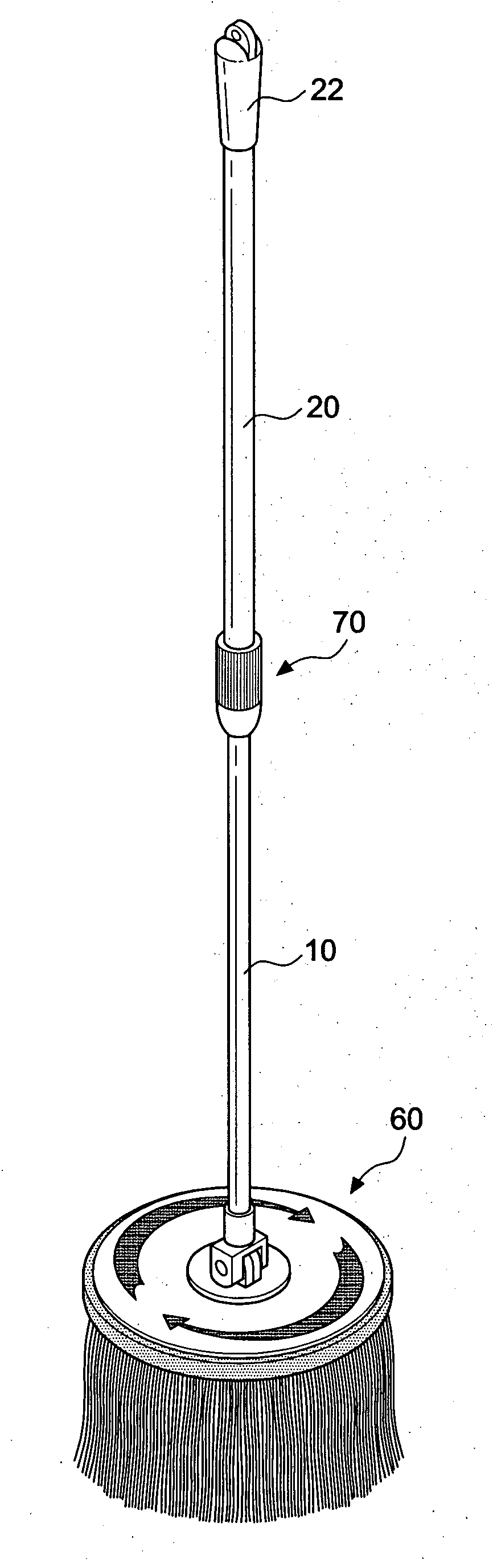
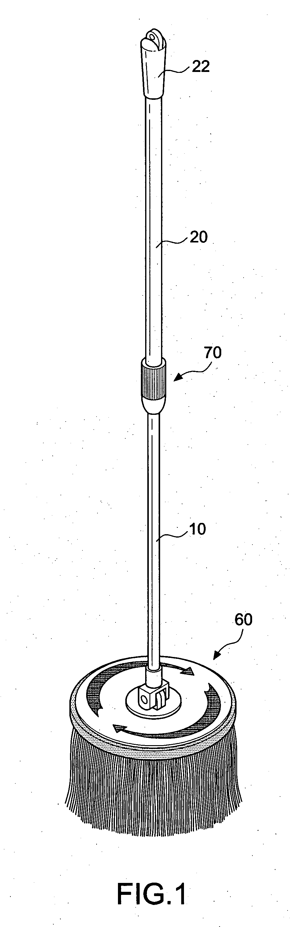
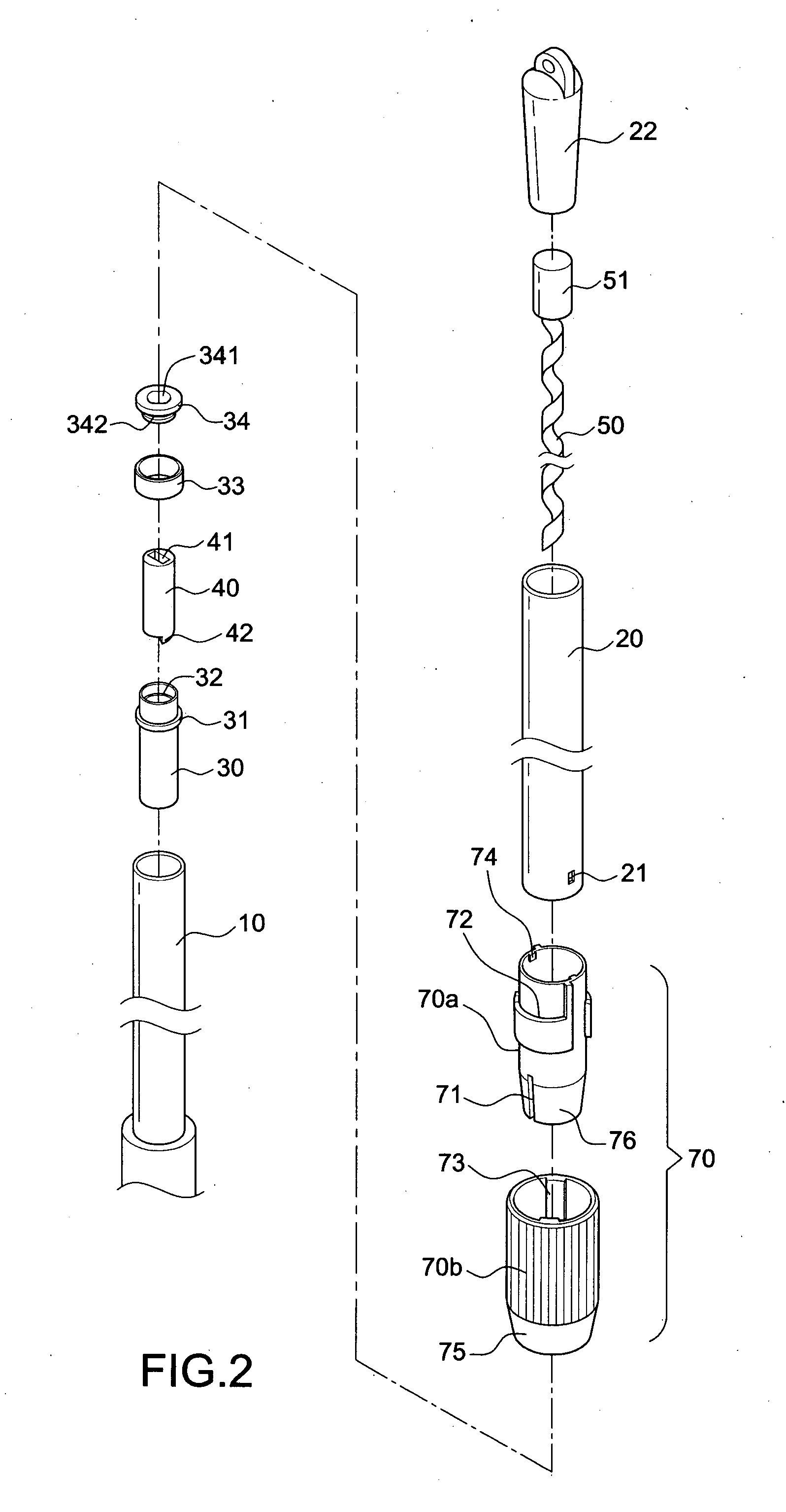
[0034]First of all, referring to FIGS. 1 through 3, a mop in accordance with the invention includes an internal rod 10, an external rod 20, an engaging element 30, a driving element 50, an actuating element40, a disc body 60, and a locking mechanism 70.

[0035]The internal rod 10 is constructed as a hollow circular tube and made by metal or non-metal material. Therefore, it can be an aluminum tube or a plastic tube.

[0036]The external rod 20 includes a bottom portion in a telescopic connection with a top portion of the internal rod 10. According to the embodiment, the operator can hold on the external rod 20 to conduct a telescopic motion on the internal rod 10.

[0037]The engaging element 30 is positioned within the opening at the top of the internal rod 10. According to this embodiment, an annular element 33 and a fixing cap 34 are mounted and fixed on the engaging element 30 after the engaging element 30 is placed within the top of the internal rod 10. The upper portion of the engagin...


PUM


Abstract

A mop with the function of dewatering the yarns by twisting in a single direction via an up-and-down linear motion, comprising: a) an internal rod; b) an external rod having a bottom portion in a telescopic connection with a top portion of the internal rod; c) an engaging element positioned within the opening at the top of the internal rod; d) a driving element formed in an elongated shape and positioned within the external rod in such a way that the driving element is moved up and down synchronically with the external rod; e) an actuating element positioned within the engaging element for accommodating the driving element, the engaging element being driven in a single direction when the actuating element is rotated by the driving element; f) a disc body secured to the bottom thereof and having mop yarns; g) a locking mechanism mounted on the external rod for locking the internal rod and the external rod in place or for unlocking them in a telescopic state, wherein the actuating element is rotated by a linear motion of the driving element when the external rod is moved up-and-down; moreover, the engaging element is driven in rotation in a single direction, thereby creating a continuous rotation of the internal rod and the disc body in the same direction by the inertia force; as a result, a centrifugal force is produced to throw away the water absorbed in the mop yarns. In this way, the mop yarns may be dewatered in a more convenient and safer way.

Description

BACKGROUND OF THE INVENTION[0001]1. Field of the Invention[0002]The invention relates to a mop with the function of dewatering the yarns by twisting in a single direction via an up-and-down linear motion, and more particularly to a structure that ensures an ergonomic operation such that the mop yarns can be dewatered in a more convenient and safe manner.[0003]2. Description of the Related Art[0004]After a mop has been used, it is necessary to wring dirty water from mop fabrics (or cotton strips) of the mop before soaking clean water again to facilitate washing a floor, and mopping is obviously a tiresome job. Therefore, related manufacturers have developed various different dewatering devices for the mop, such as a dewatering device disclosed in R.O.C. Pat. No. 347146, wherein a pedal is provided for driving a gear to rotate a dewatering tank at a fast speed, so as to wring cotton strips of the mop placed in the dewatering tank. Although the aforementioned device can improve the inc...

Claims


Application Information

Patent Timeline
Patent Type & Authority Applications(United States)
IPC IPC(8): A47L13/20
CPCA47L13/58A47L13/142
Inventor CHEN, YUNG-HUASHIN, CHIN-YANG
Owner TUO SHEN INT
Why Eureka
Try Eureka