Method and apparatus for probe tip diameter calibration

a probe tip and calibration method technology, applied in the field of coordinate measuring machines, can solve the problems of dynamic-type position errors that may occur during the calibration of the probe tip, the movement of the arm along the x-axis direction is associated with a systematically varying x-axis position error, and the movement of the arm along the y-axis direction is associated with a systematically varying y-axis position error. , to achieve the effect of improving the accuracy of measurement,

Active Publication Date: 2011-01-06
HEXAGON METROLOGY INC
View PDF20 Cites 37 Cited by
  • Summary
  • Abstract
  • Description
  • Claims
  • Application Information

AI Technical Summary

Benefits of technology

[0008]A method is provided for determining probe tip diameters with improved accuracy and reliability that may, in turn, improve the accuracy of measurements made by a CMM. Systematically-varying, dynamic-type position errors may occur during probe tip calibration. These errors are not insignificant when dealing with highly precise measurements. Performing a routine for determining probe tip diameter multiple times with the arm of the CMM in different machine positions produces different error values for systematically-varying, dynamic-type position errors because many of these errors depend on the position of the tip along the machine axes. Averaging these systematically-varying, dynamic-type position errors across routines performed at different machine positions allows more accurate measurements to be made. An average probe tip diameter measurement generated by performing a routine for determining probe tip diameter multiple times at different machine positions produces a diameter measurement that is reliably closer to the actual probe tip diameter as compared to probe tip diameter measurements arrived at through individual probe tip diameter calibration routines.

Problems solved by technology

Systematically-varying, dynamic-type position errors may occur during probe tip calibration.
Performing a routine for determining probe tip diameter multiple times with the arm of the CMM in different machine positions produces different error values for systematically-varying, dynamic-type position errors because many of these errors depend on the position of the tip along the machine axes.
Movement of the arm along the x-axis direction is associated with a systematically varying x-axis position error.
Movement of the arm along the y-axis direction is associated with a systematically varying y-axis position error.

Method used


Image

  • Method and apparatus for probe tip diameter calibration
  • Method and apparatus for probe tip diameter calibration
  • Method and apparatus for probe tip diameter calibration

Examples


example 1

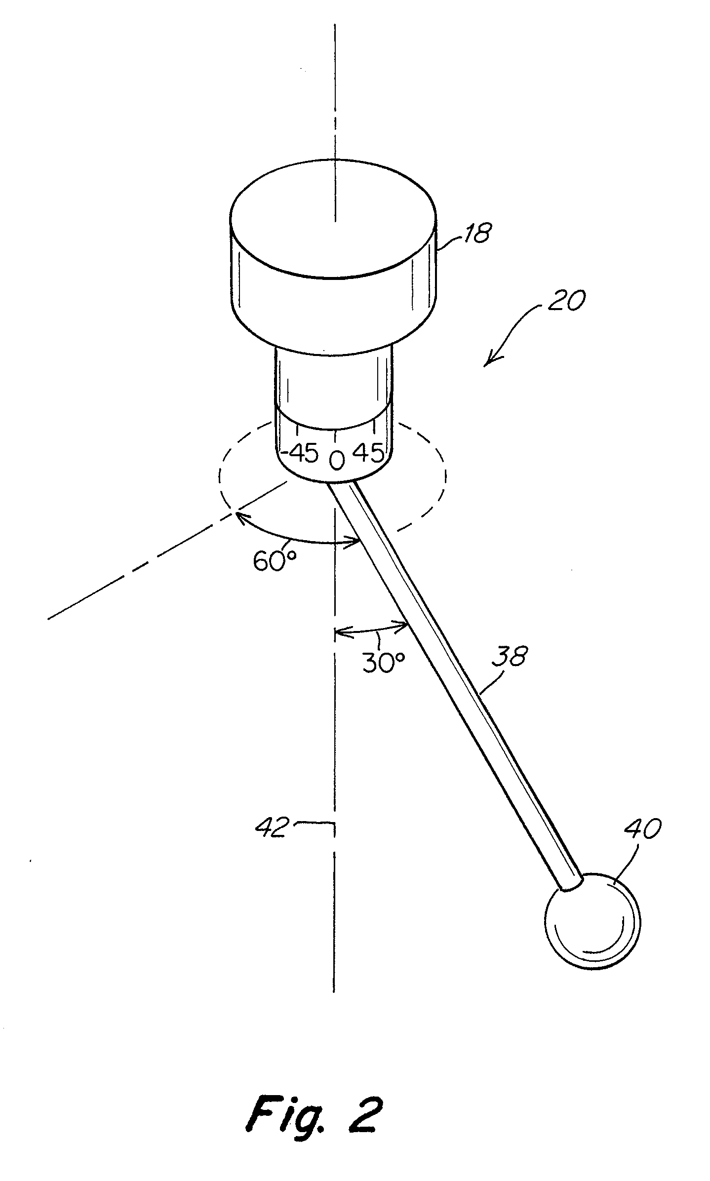
[0052]Diameter measurements were made with a probe assembly in which a 125 mm to long shaft 38 was disposed at five different angular orientations with respect to arm 18 of a CMM. These five angular orientations were associated with five different machine positions. Diameter measurements were repeated three times at each of these five different machine positions. The resulting probe diameter measurements are shown in Table 1 below. All diameter measurements are reported in millimeters. The convention used to identify a probe shaft angle includes the letter “A” followed by the angle of the probe shaft with respect to central axis 42 of arm 18 and the letter “B” followed by the rotational angle of a probe shaft about central axis 42 of arm 18.

TABLE 1Probe Diameter Measurements with Different Probe Shaft AnglesPosition 1Position 2Position 3Position 4Position 5(A0B0)(A30B135)(A30B-135)(A30B45)(A30B-45)2.99742.99662.99642.99852.99832.99772.99632.99642.99842.99802.99782.99642.99622.99842....

example 2

[0057]In a second example, the probe shaft angle was changed for each of seven probe tip calibration routines that were performed in combination with a qualifying routine for a CMM. In the qualifying routine, 20 mm gauge blocks were aligned along each of seven orientations, and a probe tip diameter calibration routine was performed prior to measuring each of the 20 mm gauge blocks. The probe shaft angle was changed for each of the calibration routines, as indicated in Table 3. The seven orientations included orientations parallel to x, y, and z axes, as well as four orientations that were at various angles to the x, y, and z axes, including a diagonal designated as (+X+Y+Z) that ran along the positive x, y and z directions, a diagonal designated as (−X+Y+Z) that ran along the negative x and positive y and z directions, a diagonal designated as (−X−Y+Z) that ran along the negative x and y directions and the positive z direction, and a diagonal designated as (+X−Y+Z) that ran in the p...


PUM


Abstract

A method for determining probe tip diameters with improved accuracy and reliability that includes performing a routine for determining probe tip diameter multiple times with the arm of the coordinate measurement machine in different machine positions. Diameter values associated with each of the calibration routines may be combined in a manner that provides more accurate diameter measurements.

Description

BACKGROUND[0001]1. Field of Invention[0002]The invention relates generally to coordinate measuring machines, and more specifically to methods and apparatuses for calibrating a probe tip of a coordinate measuring machine.[0003]2. Discussion of Related Art[0004]Coordinate measuring machines (CMM's) are in common use for dimensional inspection of workpieces. Typically, a workpiece is secured to a table, and a probe, such as one using a touch sensor, is moved in three dimensions on an arm of the CMM within a measurement volume to contact the workpiece at various points. When the probe contacts the workpiece, measuring scales in the x, y and z directions are read to obtain the position coordinates of the contacted point on the workpiece. By contacting various points on the workpiece, measurements of workpiece features can be obtained.[0005]Probe assemblies used by CMM's often include an elongated probe shaft that is mounted to the arm of a CMM at a first end, and a spherical probe tip po...

Claims


Application Information

Patent Timeline
Patent Type & Authority Applications(United States)
IPC IPC(8): G01P21/00
CPCG01B21/10G01B21/042G01B5/008
Inventor MACMANUS, RICHARD
Owner HEXAGON METROLOGY INC
Why Eureka
Try Eureka