
Dynamic optical countermeasures for ground level threats to an aircraft

a technology of optical countermeasures and aircraft, applied in the field of electronic systems, can solve problems such as exposing aircraft to threats, and achieve the effect of reducing aircraft threats

Inactive Publication Date: 2011-01-06
LOCKHEED MARTIN CORP
View PDF32 Cites 26 Cited by
  • Summary
  • Abstract
  • Description
  • Claims
  • Application Information

AI Technical Summary

Benefits of technology

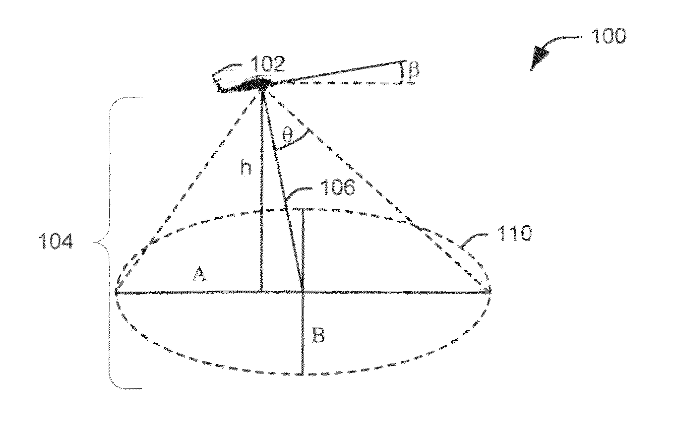
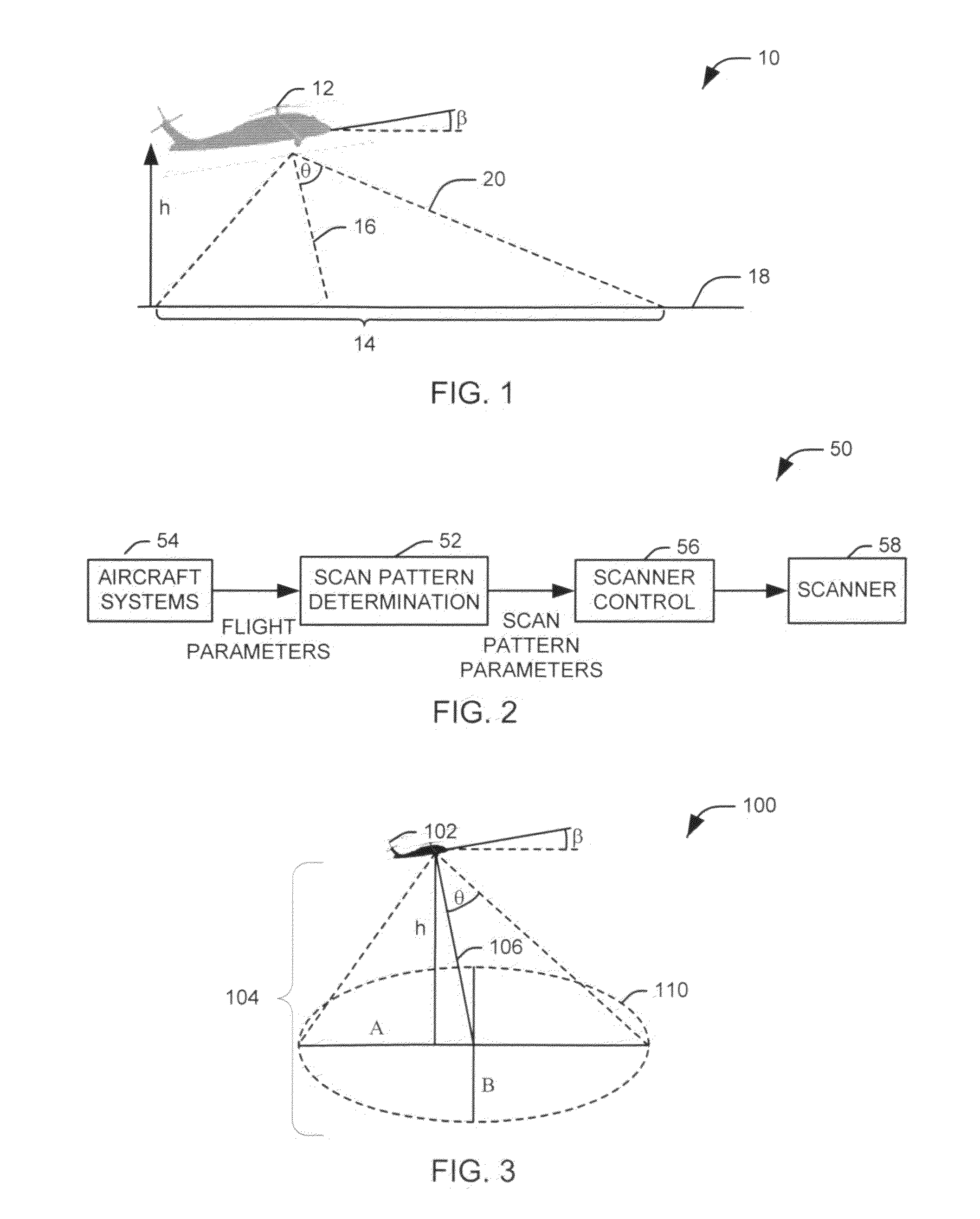
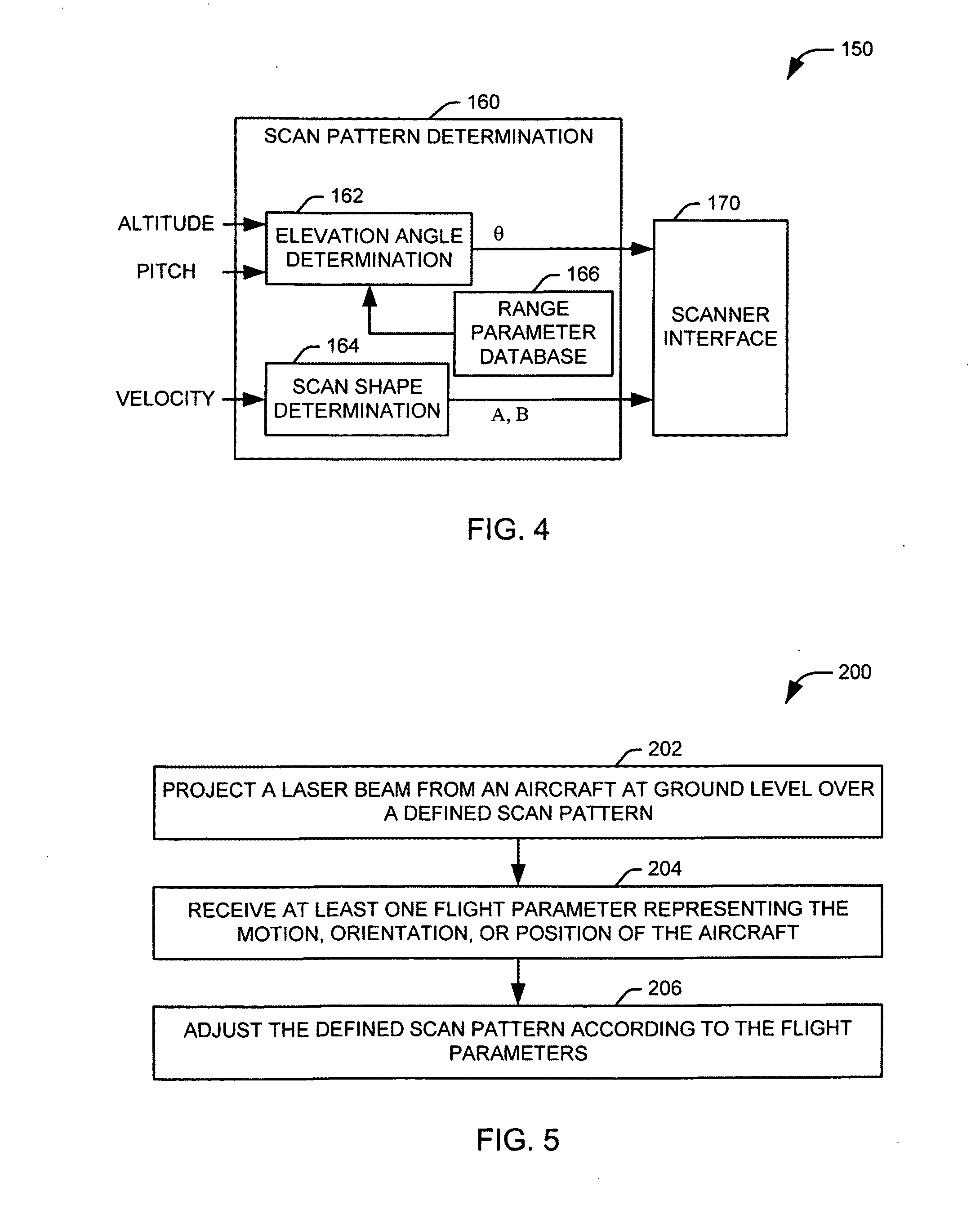
[0004]In accordance with one aspect of the present invention, a method is provided for mitigating threats to an aircraft that are located on the ground. A laser beam, having sufficient intensity to interfere with targeting of a weapon system, is projected from the aircraft over a defined scan pattern at ground level. At least one flight parameter is received. Each flight parameter represents one of a current orientation, position, and motion of the aircraft. The defined scan pattern is adjusted according to at least one flight parameter.

Problems solved by technology

For some applications, however, it is necessary to travel at comparably low altitudes for long periods of time, exposing the aircraft to threats from the ground.

Method used


Image

  • Dynamic optical countermeasures for ground level threats to an aircraft
  • Dynamic optical countermeasures for ground level threats to an aircraft
  • Dynamic optical countermeasures for ground level threats to an aircraft

Examples


Embodiment Construction

[0014]The present invention relates to systems and methods for protecting an aircraft from optically aimed threats located on the ground. For the purposes of this writing, the terms “optical” and “optically” are intended to refer to the use of light in the visible and near visible spectrum (e.g., infrared and ultraviolet). Accordingly, an optically aimed threat is a threat to an aircraft that targets an aircraft via the emission or reflection of visible, infrared, or ultraviolet light from the aircraft. It will be appreciated that a given threat can be configured to track an aircraft via any of a number of targeting modalities, including various automated systems, using optical sensors, human beings visually tracking the aircraft, and humans being assisted by equipment that improves the reception of visible light or allows for the viewing of light outside of the visible spectrum.

[0015]An optical countermeasures system can be implemented within the aircraft to interfere with one or b...


PUM


Abstract

Systems and methods are provided for mitigating optically aimed threats to an aircraft from the ground. A laser beam, having sufficient intensity to interfere with the vision of a human being, is projected from the aircraft over a defined scan pattern at ground level. At least one flight parameter is received. Each flight parameter represents one of a current orientation, position, and motion of the aircraft. The defined scan pattern is adjusted according to at least one flight parameter.

Description

TECHNICAL FIELD[0001]The present invention relates to electronic systems, and specifically relates to an optical countermeasures system for an aircraft.BACKGROUND OF THE INVENTION[0002]Aircraft are used in a wide variety of applications, both civilian and military, including travel, transportation, fire fighting, surveillance, and combat. Various aircraft have been designed to fill the wide array of functional roles defined by these applications, including balloons, dirigibles, traditional fixed wing aircraft, flying wings and helicopters.[0003]In general, aircraft travel at a sufficient altitude to substantially eliminate any threat posed to the aircraft from threats posed by personnel on the ground. For some applications, however, it is necessary to travel at comparably low altitudes for long periods of time, exposing the aircraft to threats from the ground. Similar exposure takes place in other applications during take-offs and landings of the aircraft.SUMMARY OF THE INVENTION[00...

Claims


Application Information

Patent Timeline
Patent Type & Authority Applications(United States)
IPC IPC(8): G21G5/00
CPCF41H11/02G01S7/495F41H13/0056
Inventor HERMAN, CARL R.MORAITES, STEPHEN C.
Owner LOCKHEED MARTIN CORP
Learn More