Device and Method for Determining a Failure Mode of a Pneumatic Control Valve Assembly

a technology of pneumatic control valve and failure mode, which is applied in the direction of valve operating means/releasing devices, functional valve types, service pipe systems, etc., can solve the problems of control valve assembly control fluid leakage, more costly and time-consuming repair of control valve diaphragm itself, and the inability of positioning devices to distinguish between certain types of control fluid leakage within the control valve assembly

Active Publication Date: 2011-01-06
FISHER CONTROLS INT LLC
View PDF13 Cites 35 Cited by
  • Summary
  • Abstract
  • Description
  • Claims
  • Application Information

AI Technical Summary

Problems solved by technology

If a deviation between the actual position and the desired set point is detected which will result in an undesirable flow through the valve, the positioner sends a fluid signal to the actuator to adjust the position of the metering device accordingly.
While known smart positioners are capable of detecting certain general malfunctions in a control valve, these positioners are not capable of distingu...

Method used


Image

  • Device and Method for Determining a Failure Mode of a Pneumatic Control Valve Assembly
  • Device and Method for Determining a Failure Mode of a Pneumatic Control Valve Assembly
  • Device and Method for Determining a Failure Mode of a Pneumatic Control Valve Assembly

Examples


Embodiment Construction

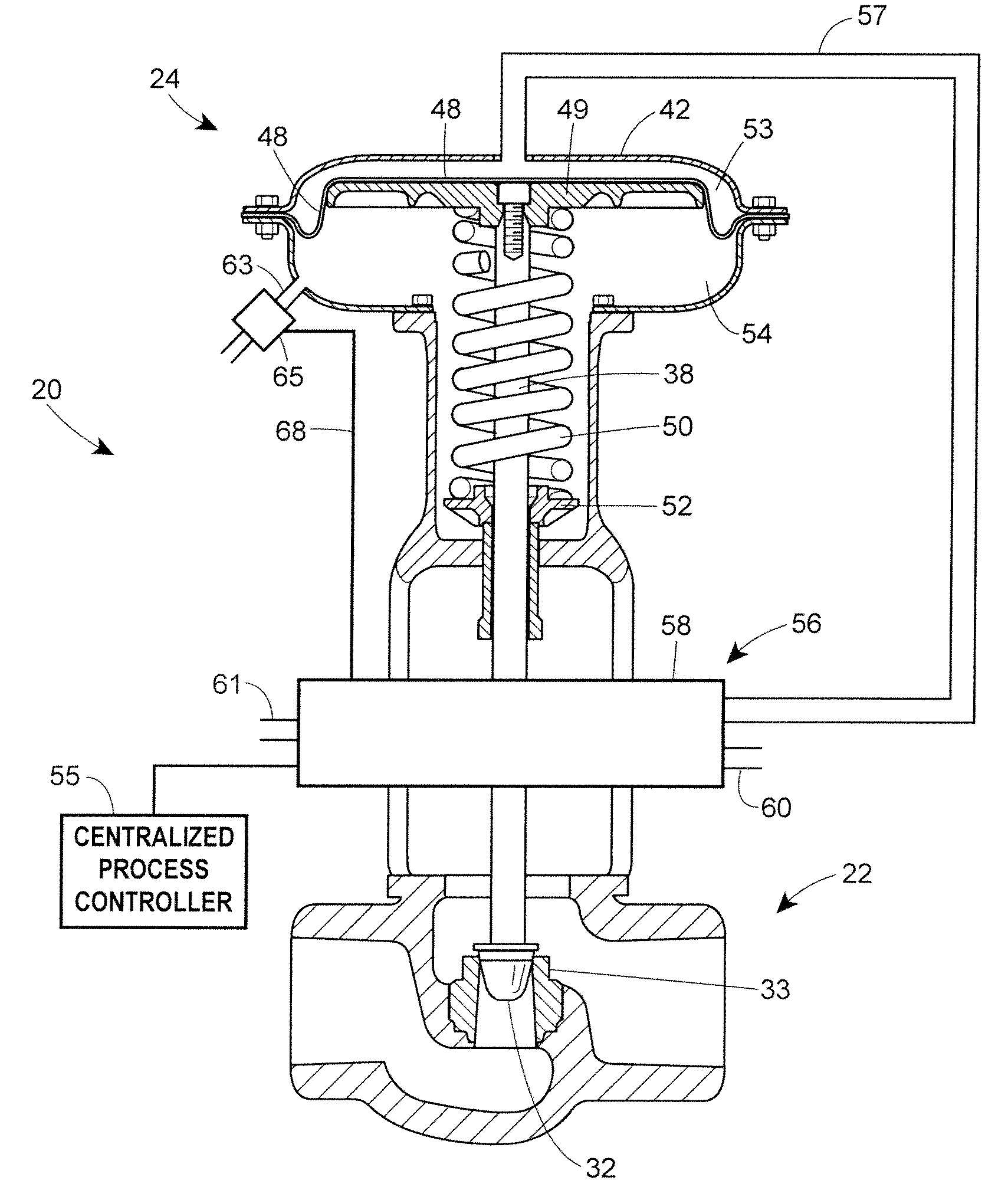
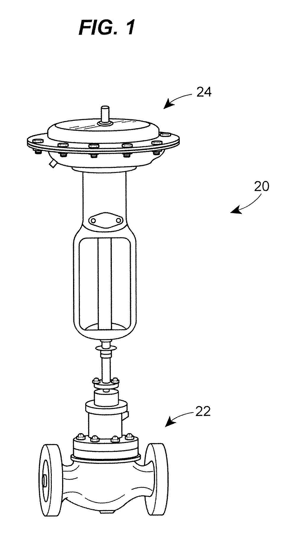
[0015]Referring now to the drawings and with specific reference to FIG. 1, a control valve assembly is generally referred to by reference numeral 20. The control valve assembly 20 includes a control valve 22 to which a control valve actuator 24 is attached. While the control valve assembly 20 described herein will be referred to as a sliding stem type of control valve, the teachings of the disclosure can be used in conjunction with other types of control valves, including but not limited to, rotary valves, butterfly valves, and the like.

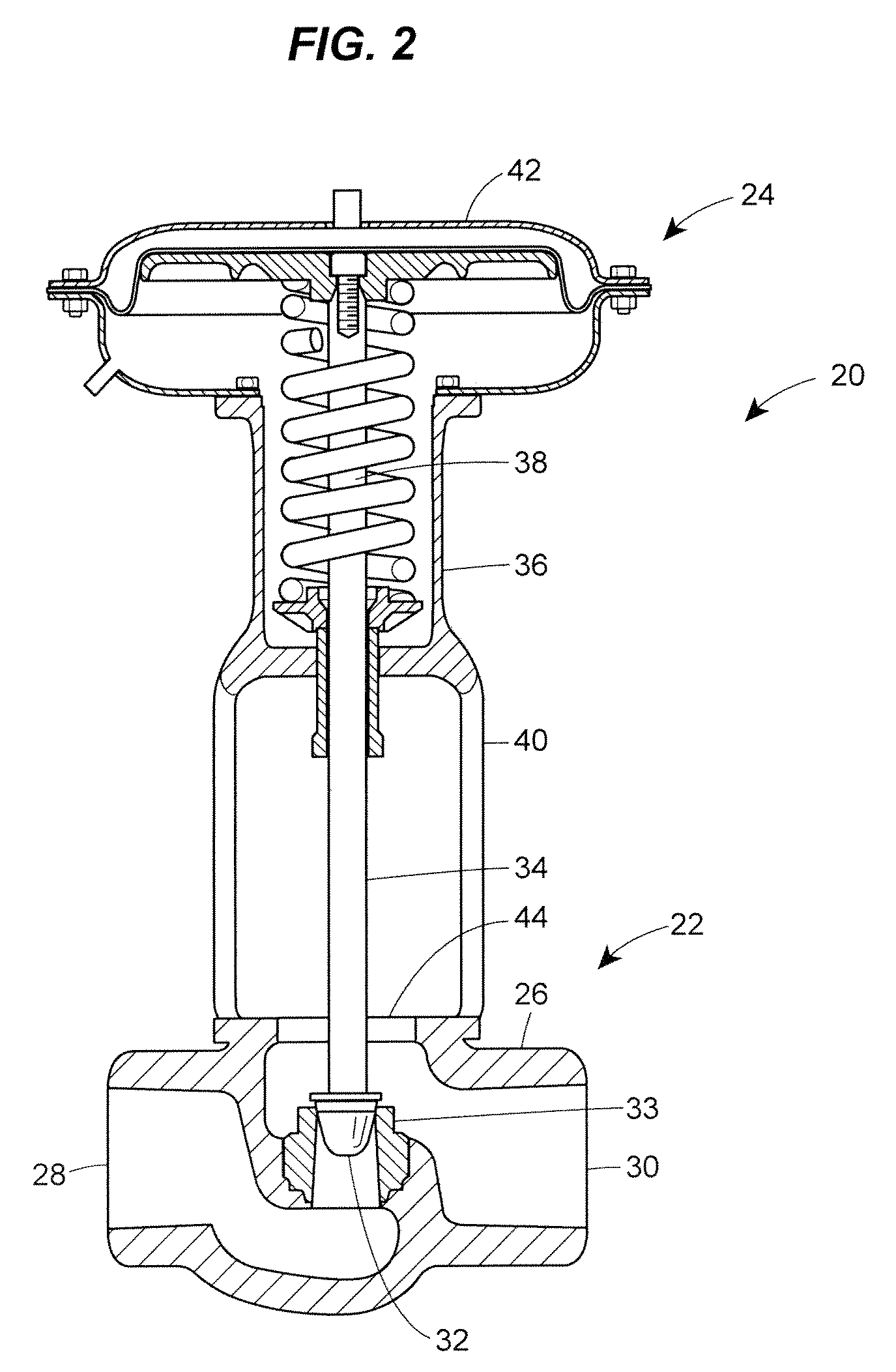
[0016]Referring now to FIG. 2, the control valve 22 is shown in further detail to include a housing 26 having an inlet 28 and an outlet 30. While not shown, it is to be understood that the valve 22 is adapted to allow fluid to flow from the inlet 28 to the outlet 30, and that by adjusting the position of a valve plug 32 slidably disposed within the housing 26, the volume and rate at which the fluid flows therethrough can be adjusted as well. The posi...


PUM


Abstract

A control valve assembly is capable of diagnosing malfunctions in the control valve assembly and discerning a location of a control fluid leak in the control valve assembly. The control valve assembly includes a control valve, an actuator and a positioner. The actuator includes an actuator vent in an actuator housing, the actuator vent being connected to a flow switch. By determining a flow condition through the actuator vent, the positioner determines whether a control fluid leak is located in a control line or in a diaphragm.

Description

FIELD OF THE DISCLOSURE[0001]The disclosure generally relates to control valve assemblies and, more particularly, to control valve assemblies that diagnose and report failure modes in a control valve.BACKGROUND OF THE DISCLOSURE[0002]Process control valves are used in myriad industrial applications for controlling the flow of a fluid. For example, in chemical processing plants or oil refineries, control valves are used to manipulate a flowing fluid to compensate for increases or decreases in demand, or other load disturbances, and thus keep the fluid flow regulated.[0003]The control valve is typically provided as part of a control valve assembly having a control valve, a control valve actuator, and a positioner. The control valve includes an inlet and an outlet, with a movable valve plug therebetween. By adjusting the position of the valve plug, fluid flow through the valve is adjusted. The control valve actuator typically includes a stem connected to the valve plug and provides the...

Claims


Application Information

Patent Timeline
IPC IPC(8): F16K31/02
CPCF16K37/0066F16K31/1262Y10T137/5762Y10T137/8326
Inventor WILKE, GALEN D.
Owner FISHER CONTROLS INT LLC
Why Eureka
Try Eureka