Passive magnetic bearing

a magnetic bearing and passive technology, applied in the direction of bearings, shafts and bearings, dynamo-electric machines, etc., to achieve the effect of low hysteresis effects or losses, removal or minimization of hysteresis effects, and high electrical resistivity valu

Inactive Publication Date: 2011-01-06
STEORN
View PDF17 Cites 18 Cited by
  • Summary
  • Abstract
  • Description
  • Claims
  • Application Information

AI Technical Summary

Benefits of technology

[0011]This system is of a magneto-mechanical nature and requires no circuitry. It has a variety of applications which require a friction minimizing bearing operation. The removal of friction through the levitation effect exhibited by this magnetic bearing system through the non-contact nature of the shaft and its attached less large ring magnet, coupled with the passive nature of this system, allows for non-contact rotation for both low and high speed systems integration.
[0012]One of the known impediments to such a system is eddy current losses and to counter these, materials within the system are chosen for their lack of conductivity and / or are of a high electrical resistivity value. Another issue typical of a magnetic bearing system is losses due to hysteresis effects which in turn are due to changing magnetic fields. Such hysteresis effects are removed or minimized to such an extent that they are not a significant loss due to reduced magnetic field changes directly related to the fact that the large and less large ring magnets are radially restrained in a stable repulsive magnetic field by said magnetic field interaction and also that the axial movement of the less large ring magnet is substantially reduced, such that the overall magnetic bearing systems operates in a manner that allows for a near zero force to be acting on the two ring magnets and as such the system exhibits little or no magnetic field changes and thus little or no hysteresis effects or losses.
[0013]Due to the rigid nature of this magnetic bearing system, this system can be used as a single unit or in a plurality of implementations and the related magnetic levitation of the shaft allows for little or no contact on the shaft pivot points, thereby vastly reducing or completely diminishing pivot point friction.

Problems solved by technology

At the other end of the spectrum, advances in magnetic materials and magnetic levitation technology have given rise to active magnetic bearings which overcome the issues associated with direct contact between moving parts although they present a different set of challenges related to their complex control requirements.

Method used


Image

  • Passive magnetic bearing
  • Passive magnetic bearing
  • Passive magnetic bearing

Examples


Embodiment Construction

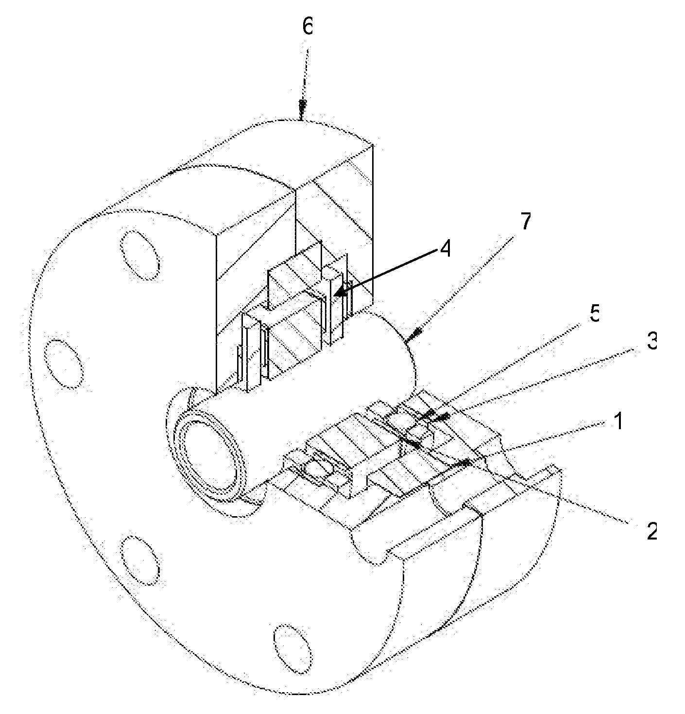
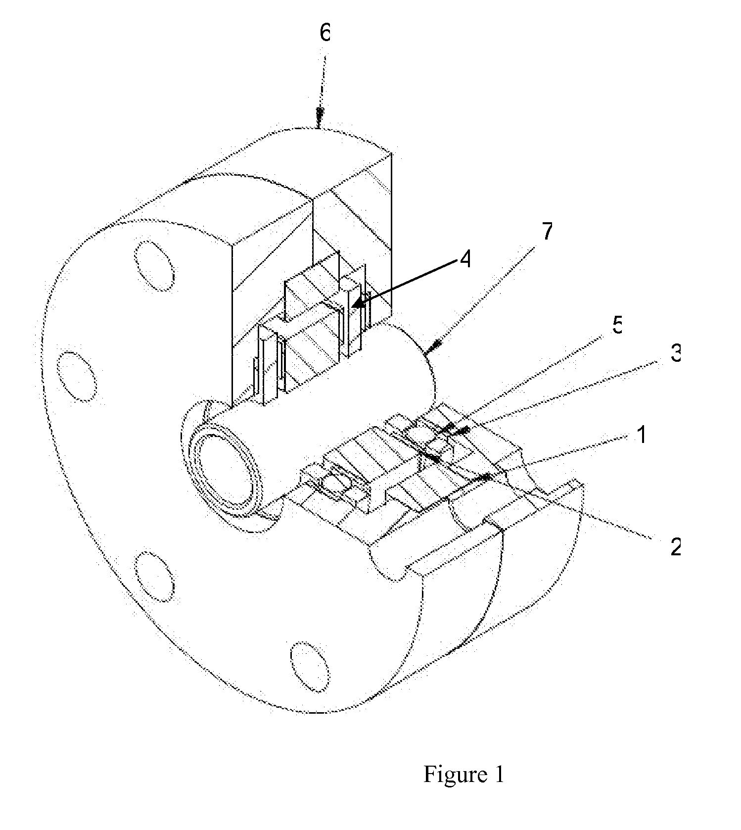
[0019]In accordance with one embodiment of the present invention a large axially magnetized ring magnet 1 and a less large axially magnetized ring magnet 2 are positioned inside a housing 6. The housing 6, manufactured from Acetal, is circular in shape with a diameter of 43 mm and a depth of 9 mm comes in two pre-manufactured parts, which are mirror images of each other. Each housing piece exhibits three step-down cut outs. The largest of these is found 8 mm from the outer diameter of the housing piece. This first cut out has a diameter of 30 mm, the second largest cut out has a diameter of 24.4 mm and the smallest has a diameter of 11.5 mm. It is within these cut outs in this illustrative embodiment that the various bearing components are housed.

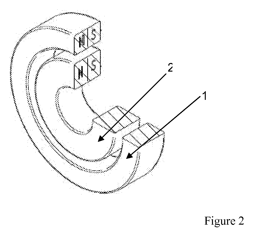
[0020]As shown in FIG. 2 the two ring magnets 1 and 2 exhibit at least one pair of north and south poles. The two magnets 1 and 2 have the same width and are constrained within the housing such that the both the outer and inner edges of the...


PUM


Abstract

A passive magnetic bearing which has an exceptionally low friction couple. Radial and axial restraint is achieved through magnetic and mechanical means. The embodiment of the passive magnetic bearing has two axially magnetized rings, which each exhibit at least one pair of north and south poles. The magnetized rings are positioned in a manner where the poles are in a repulsive magnetic interaction such that the plane of symmetry which separates the like poles lies perpendicular to the axis of the rotation of a shaft and this radially constrains the movement of the shaft. Axial rigidity is added to the system by the use of ceramic bearings and related axial retaining mechanisms on one of the ring magnets thus maintaining the magnetic bearing in an otherwise unstable axial plane.

Description

FIELD OF THE INVENTION[0001]The present invention is in the field of bearings systems, and more particularly relates to passive magnetic bearings for providing radial and axial restraint in rotary systems.BACKGROUND OF THE INVENTION[0002]This invention relates to control of rotating mechanical systems, specifically the requirement to restrain the relative movement of two or more elements of such a system. A wide variety of bearings exist which attempt to address this requirement, ranging from simple ball bearings to complex electromagnetic assemblies.[0003]Ball bearings are well known in the art and are utilized in thousands of devices. Improvements in materials technology, such as the use of ceramics, and enhanced raceway designs have addressed many of the inherent issues with traditional bearings, such as friction and lubrication.[0004]At the other end of the spectrum, advances in magnetic materials and magnetic levitation technology have given rise to active magnetic bearings whi...

Claims


Application Information

Patent Timeline
Patent Type & Authority Applications(United States)
IPC IPC(8): H02K7/09
CPCF16C19/10F16C32/0402F16C32/0425
Inventor MCCARTHY, SEANFLANAGAN, SEAMUSSIMPSON, ALANSORIN, MAXIME
Owner STEORN
Why Eureka
Try Eureka